
- a) Install the camshaft in the engine and secure it with bearing caps;
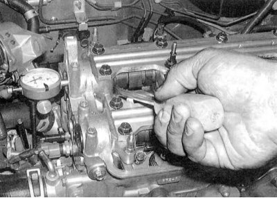
- b) Fix the dial gauge on the cylinder head, resting it with a plunger on the end of the shaft (see accompanying illustration);
- c) Using a large screwdriver as a lever, pull the shaft all the way back and zero the meter, then push the shaft forward and read the instrument reading;
- d) Compare the measurement result with the requirements Specifications;
- e) Excessive axial play indicates wear on the camshaft or head. Replace defective components.
2. To check lateral runout:
- a) Lay the camshaft removed from the engine in two V-shaped prisms, then press the plunger of the dial gauge against the neck of the central bearing and measure the amount of runout when the shaft rotates;
- b) Compare measurement results with requirements Specifications;
- c) In case of excessive combat, the camshaft must be replaced.
Engine V18V1 (without VTEC)
Withdrawal
1. Remove the distributor (see chapter Engine electrical equipment).
2. Remove the cylinder head cover (see Removal and installation of a cover of a head of cylinders). Loosen the valve adjusting screws completely (see chapter Current service).
3. Bring the piston of the first cylinder to the TDC position (see Bringing the piston of the first cylinder to the top dead center position (TDC)).
4. Remove the timing belt and camshaft gears (see Removing, checking the condition and installing the gas distribution belt and timing gears).
5. Check the shaft bearing caps for arrow markings pointing towards the timing belt. If necessary, apply the appropriate marks yourself using a scriber. Also number the lids (from the first to the sixth in the direction from the timing belt) and mark them as belonging to a specific shaft (inlet or outlet).
Attention! Improper installation of shaft holders, as well as rotation of the latter in the wrong direction, can lead to jamming of the assemblies.
6. Moving from the center outward, in several steps (1/4 turn per approach) loosen the cap bolts, reducing the force developed by the valve springs to zero.
7. Remove the camshafts from the cylinder head, then remove the rocker arms (mark the landing position of the latter - during assembly, they must be installed strictly in their original places).
Examination
1. Thoroughly wipe all components and check them for signs of wear and mechanical damage. Check up a condition of working surfaces of yokes and cams of camshafts. Check up a condition of axes of yokes. Replace defective components. Do not forget to make sure that the oil flows of the rocker axles are passable.
2. Assess the degree of wear of the camshaft cams:
- a) Check the cam lifts for deep scratches, nicks, gouges, and signs of uneven actuation;
- b) In case of defects, replace the shaft, having previously found out and eliminated the cause of wear. Check the engine oil for the presence of an abrasive in it, make sure that the oil flows are passable. Cam wear is most often associated with oil contamination;
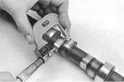
- c) Using a micrometer, measure the height of the cams (see accompanying illustration). 3. Check bearing journals and shaft and bearing caps for nicks and signs of uneven wear. If defects are found, replace the cylinder head.
4. Measure the running clearances in the bearings using the gauge wire from the Plastigauge kit:
- a) Wipe the bearing caps and shaft journals with a clean cloth soaked in acetone;
- b) Carefully place the shafts in the cylinder head (without any lubrication).
Note. During the procedure, the shafts should not rotate.
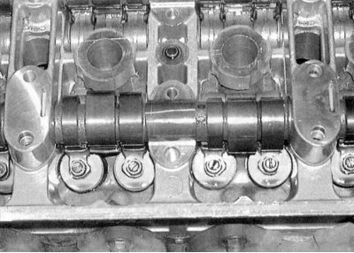
- c) Lay lengths of calibrated plastic wire from the Plastigauge set along the bearing journals of the shaft (see accompanying illustration);
- d) Install the bearing caps, then tighten their fasteners to the required torque in several steps (move from the center of the shaft outwards);
- e) Give bolts and remove covers;
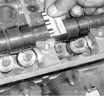
- f) Measure the width of the flattened pieces of calibrated wire using the scale printed on the kit package (see accompanying illustration);
- g) If the measurement results are out of range (see Specifications), replace worn components;
- h) With the edge of a credit or payphone card, scrape off the remnants of the flattened wire from the necks of the shaft.
Installation
1. Lubricate all components with assembly grease or clean engine oil, then install the rocker arms in place (follow the boarding mark).
2. Lubricate the cams and journals of the camshafts with special assembly grease, then place the shafts in their bearings (do not confuse the intake shaft with the exhaust). Lubricate the surfaces of the covers of the 1st and 6th bearings mating with the head with an anaerobic sealant. Install the covers, then, moving from the center outward, evenly tighten the fixing bolts in several steps to the required torque (see Specifications).
3. Further installation is carried out in the reverse order to the dismantling of the components. Adjust valve clearances if necessary (see chapter Current service).
4. Run the engine for signs of leaks and for proper operation.
Engines V18S1 and V18S5 (VTEC)
Withdrawal
1. Remove the timing belt and gears (see Removing, checking the condition and installing the gas distribution belt and timing gears).
2. Remove the cylinder head cover (see Removal and installation of a cover of a head of cylinders).
3. Remove the ignition distributor and crankshaft fluctuation sensor (see chapters Engine electrical equipment and Engine management systems).
4. Loosen the locknuts and turn out the valve clearance adjustment bolts until they stop.
5. Check the shaft bearing caps for arrow markings pointing towards the timing belt. If necessary, apply the appropriate marks yourself using a scriber. Also number the lids (from the first to the sixth in the direction from the timing belt) and mark them as belonging to a specific shaft (inlet or outlet).
Attention! Improper installation of shaft holders, as well as rotation of the latter in the wrong direction, can lead to jamming of the assemblies.
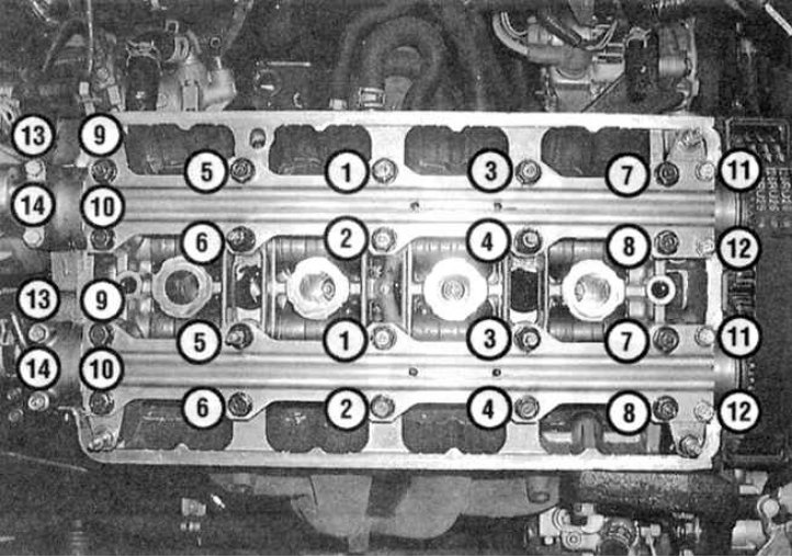
6. Moving from the center outward, in several steps (1/4 turn per approach) loosen the cover bolts, reducing the force developed by the valve springs to zero (see illustration - bolts should be removed in the reverse order shown in the picture). Remove retainer plates and bearing caps (the mating surface of the 3rd [centre] bearing cap is equipped with a guide pin equipped with a rubber o-ring - be careful not to lose small parts). 7. Remove the camshafts from the cylinder head.
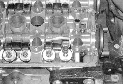
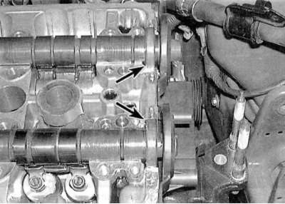
8. Fasten the rocker arms of the actuator of each of the valve sets to each other using rubber bands (see accompanying illustration). 9. Turn out bolts of fastening of a head of cylinders passing through axes of yokes (see Removal and installation of a head of cylinders). Remove the oil sprayers from the axles (see Removal, condition check and installation of camshafts and rocker arm assembly).
10a. Screw 12 mm bolts into the ends of the axles.
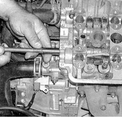
10b. For heads of bolts one by one take an axis from a head of cylinders see accompanying illustrations).
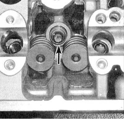
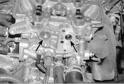
11. Remove the valve clearance corrector assembly from their sockets in the cylinder head (see accompanying illustration). Check build status (see VTEC Systems - General Information and Component Health Check).
Examination
1. Check the condition of the shafts and rockers (see check paragraphs for the B18B1 engine (without VTEC) higher).
2. Disassemble the rocker arm kits and check the condition of the components (see VTEC Systems - General Information and Component Health Check).
Note. Put the components in the order they belong to your kit - when assembling, they must be installed strictly in their original places. After making sure that the parts are in good condition, assemble the kits and fasten them together with rubber bands.
Installation
1. Install the valve clearance correctors in their regular places (see previous illustration).
2. Lubricate all components with assembly grease or clean engine oil. Completely loosen the valve clearance screws. Reinstall the rubber banded rocker arm assemblies in their original locations, then install the rocker axles. In each of the axes of the rocker arms there is a nest for landing an oil sprayer. If, after installing the shafts, the nests turn out to be misaligned, correct the axles for the heads of the bots screwed into their ends.
3. Install new O-rings on the nozzles, then install the nozzles in the head - do not confuse the inlet nozzle with the outlet (see VTEC Systems - General Information and Component Health Check). Make sure that the nozzles fall into their nests in the axes of the rocker arms (when properly installed, the atomizers should block the axles from turning).
4. Lubricate the cams and journals of the camshafts with special assembly grease, then place the shafts in their bearings (do not confuse the intake shaft with the exhaust).
5. Thoroughly wipe the seal contact surfaces of the head with a dry cloth and install new seals (spring-equipped sides towards the head) (see accompanying illustration). 6. Lubricate the surfaces of the 1st and 5th bearing caps mating with the head with an anaerobic sealant.

7. Install the holders on the covers, then, proceeding in the indicated order (see accompanying illustration), in several stages, evenly tighten the fixing bolts to the required torque (see Specifications).
8. Further installation is carried out in the reverse order to the dismantling of the components. Adjust valve clearances if necessary (see chapter Current service).
9. Run the engine for signs of leaks and for proper operation.