
General information
Many of the Honda models are equipped with an electronic valve timing adjustment system (VTEC).
The difference between conventional engines and VTEC equipped engines lies in the configuration and principle of operation of the valve train. The design of the engine block and all attachments and assemblies, as well as the schemes for organizing lubrication and cooling systems on both units are the same. An engine externally equipped with a VTEC system is distinguished by the presence of a convex inscription of the corresponding content on top of the cylinder head cover (VTEC).
The intake camshaft is equipped with three cams for each of the valves it drives. Dedicated power control module (RSM), based on the data coming from the information sensors, determines which of the sets of cams at each current moment should drive the inlet valves of the combustion chambers. Based on the analysis of the incoming information, the PCM turns the VTEC system on or off.
The following are used as initial parameters that determine the functioning of VTEC:
- a) Engine speed (rpm);
- b) Vehicle speed (mph);
- c) Throttle position sensor output (TPS);
- d) The current load on the engine, determined by the readings of the absolute pressure sensor in the intake manifold (IDA);
- e) Coolant temperature.
At low engine speeds, both the primary and secondary intake valves are actuated by their own cams and open to the same height and for the same duration, providing good low end torque and fast gas response.
When it becomes necessary to increase the output of the engine, the rocker arms of the primary and secondary intake valves are blocked with an intermediate rocker by means of a special hydraulic device with electronic control. In this case, the duration and height of the opening of both valves is determined by the shape of the intermediate cam, which is characterized by a greater height and a smaller peak of the lift.
Note. The primary and secondary rocker arms stop making contact with their own cams until the system is shut down. The system allows you to achieve optimal torque at both low and high engine speeds, depending on the current load applied to it.
Checking the Status of Components
Lockout Solenoid/Pressure Switch
The solenoid valve for blocking the VTEC system, which includes a pressure switch, is located on the left side of the rear wall of the engine (from the bulkhead of the engine compartment).
Models 1994 and 1995 issue
Malfunctions in the VTEC lockout solenoid circuit cause a DTC to be set (DTC) 21 in the memory of the control unit. At the same time, the control lamp on the instrument panel of the car lights up "Check engine". Detailed information on DTC self-diagnosis systems is given in Chapter Engine management systems.
Pressure switch failure causes DTC 22 to be stored and warning light to come on "Check engine".
Models since 1996 vol.
Failure in the circuits of the solenoid valve or the pressure sensor-switch leads to the operation of the warning lamp "Check engine" and writing to the memory of the DTC P1259 control unit. An OBD II scanner is required to read diagnostic codes (see chapter Engine management systems).
All models
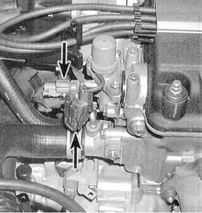
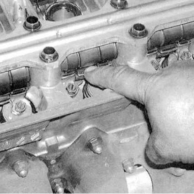
1. Disconnect the round electrical connector for two pressures (see accompanying illustration). 2. Connect an ohmmeter between the sensor-switch terminals. The device should detect the presence of conductivity (zero resistance), otherwise the sensor-switch must be replaced.
3. Connect a voltmeter between the body ground and the blue-black wire terminal in connector e on the harness side. With the ignition on (key in ON position) the device should show 12 V, otherwise check the condition of the blue-black wire and the reliability of its contact connections in the area between the connector and the terminal on the PCM.
4. If the voltage test is positive, connect a voltmeter between the two terminals of the connector on the harness side (blue-black and black wires). With the ignition on, the device should fix 12 V, otherwise check the condition of the black wire (grounding) and the reliability of its contact connections in the area between the connector and the mass.
5. With the ignition off (key in OFF position) disconnect the VTEC lockout solenoid valve 1-pin connector (see illustration above). Connect an ohmmeter between the valve terminal (no connector) and body weight. If reading is outside the 14 to 30 ohm range, replace the solenoid valve (see below).
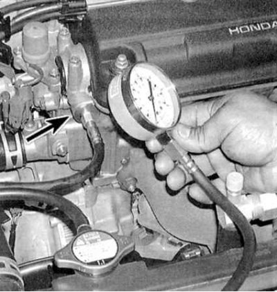
6. Remove the 10 mm bolt from the oil pressure control port on the solenoid valve. Connect a mechanical oil pressure gauge to the fitting (see accompanying illustration). 7. Warm up the engine to normal operating temperature (cooling fan should run).
8. In short jerks, alternately raise the engine speed to 1000, 3000 and 5000 per minute. Read the gauge reading at each of the listed engine speeds.
Attention! Do not increase the engine speed without load for more than one minute.
9. The oil pressure should not exceed 0.49 kgf/cm2, otherwise check the condition of the VTEC solenoid valve.
10. Connect a jumper wire between the positive battery terminal and the VTEC solenoid valve terminal (see illustration for paragraph 1). Raise the engine speed to 5000 rpm for a short time (no more than one minute) and read the pressure gauge. This time it should be at least 4.2 kgf/cm2, otherwise check the condition of the valve.
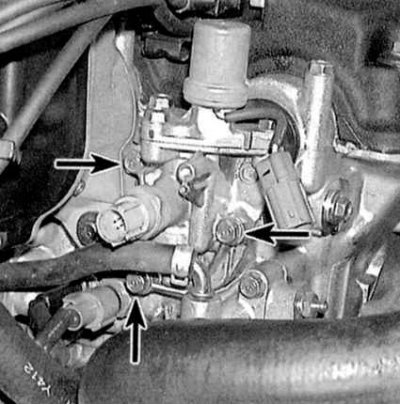
11a. Remove the solenoid valve assembly, separate the pressure switch from it.
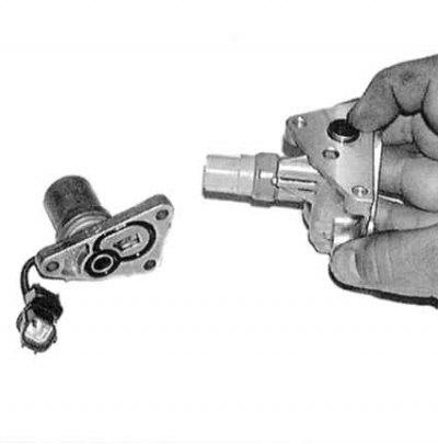
11b. Manually check the freedom of movement of the plunger (see accompanying illustrations). Be sure to replace the O-ring when reinstalling the assembly. 12. Check the condition and patency of the full flow oil filter. Clean the filter and reinstall it (with new sealing ring). If the filter is blocked, change the engine oil.
Rocker arms with oil sprayers
1. Remove the cylinder head cover (see Equipment and controls in the cabin) and bring the piston of the first cylinder to the TDC position (see Seat adjustment).
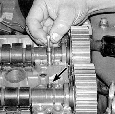
2. Press the intermediate rocker with your finger (see accompanying illustration) - it must move freely from the rocker arms of the primary and secondary valves. Otherwise, remove the rocker arms to check the condition of the assembly components (see Removal, condition check and installation of camshafts and collection ki rocker).
3. After removing the rocker arms (see Bonnet release) remove the synchronizing pistons from them (see accompanying illustration).
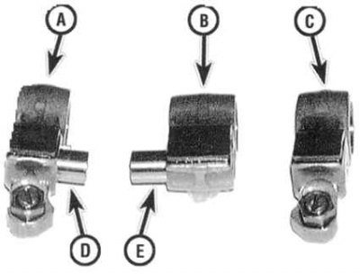
A) Primary valve rocker
IN) secondary valve rocker
WITH) intermediate rocker
D) short piston
E) long piston
4. Check all components (rocker arms and pistons) for signs of wear, scoring and signs of overheating. Replace defective parts. Remove the oil sprayers from the intake and exhaust sides of the cylinder head (see accompanying illustration), clean them and reinstall them. 5. Assembly is carried out in the reverse order to dismantling.
Note. Before installing the rocker arm kits on the axle, assemble them and fasten them with rubber bands (see Bonnet release).
Valve clearance adjusters
1. Four sets of valve clearance adjusters are installed in the cylinder head.
2. Remove individual corrector assemblies (see Bonnet release).
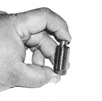
3. Use your fingers to check the freedom of movement of the corrector assembly plunger (see accompanying illustration) - slight resistance should be felt, however, with an increase in load, the plunger should be squeezed out without hindrance. If defects are found, replace the assembly.