
Attention! Wait until the engine has completely cooled down before starting work.
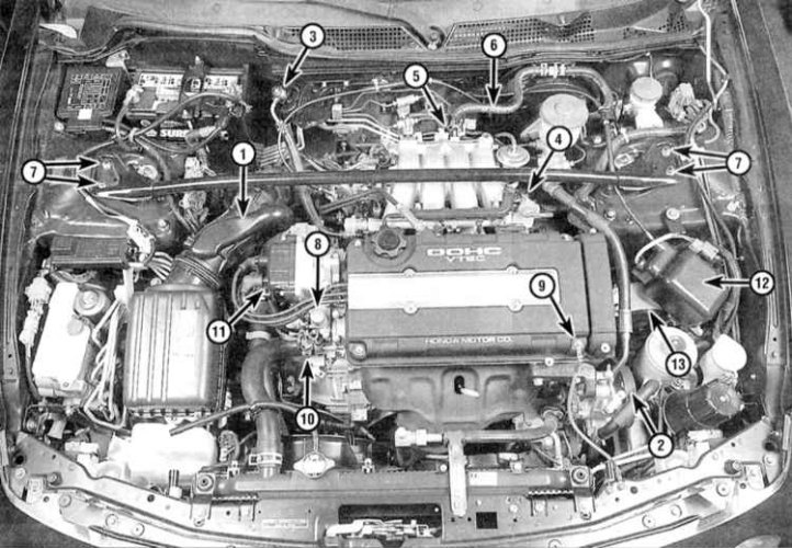
Vehicle engine compartment components to be dismantled when removing the cylinder head
1 - Inlet air intake; 2 - Steering pump; 3 - Fuel supply line; 4 - Fuel return line; 5 - PCV hose; 6 - Vacuum hose of the brake booster; 7 - Fasteners of the spacer bar; 8 - Solenoid valve/sensor - VITEC pressure switch; 9 - Engine ground bus; 10 - Hose of the cooling path; 11 - Ignition distributor; 12 - Actuating device of the tempostat; 13 - The upper support of the power unit
Withdrawal
1. Bring the piston of the first cylinder to the TDC position of the end of the compression stroke (see Bringing the piston of the first cylinder to the top dead center position (TDC)).
2. Disconnect the negative cable from the battery and the ground bar from the engine (see illustration above).
Attention! If the stereo system installed in the car is equipped with a security code, before disconnecting the battery, make sure that you have the correct combination to activate the audio system!
3. Empty the cooling system and remove the spark plugs (see chapter Current service).
4. Remove the air cleaner with air intake sleeve (see chapter Power and exhaust systems).
5. Remove accessory drive belts (see chapter Current service). Loosen the steering pump and move it aside without disconnecting the hydraulic lines, then remove the steering pump bracket (see chapter Suspension and steering).
6. Disconnect the accelerator cable and release the pressure in the power system (see chapter Power and exhaust systems).
7. Disconnect the following hoses and lines (see chapters Power and exhaust systems and Engine management systems):
- a) Fuel supply and return hoses;
- b) evaporative emission hose (EVAP);
- c) ventilation hose (breather pipe);
- d) PCV hose.
- e) Vacuum hose for brake booster.
8. Disconnect the coolant bypass hose, heater hose and upper radiator hose (see chapter Cooling and heating systems).
9. On VTEC models, remove the spacer bar installed across the engine compartment (see part General and overhaul of the engine this chapter).
10. Disconnect the electrical wiring from the following components:
- a) fuel injection injectors;
- b) coolant temperature sensor (CTS);
- c) Temperature meter sensor;
- d) TDC sensor / position of the crankshaft and camshafts;
- e) Crankshaft fluctuation sensor;
- f) Ignition coil;
- g) Throttle position sensor (TPS);
- h) Absolute pressure sensor in the pipeline (IDA);
- i) EVAP charcoal canister purge solenoid valve;
- j) VTEC solenoid valve (18C1 and 18C5));
- k) VTEC pressure switch (18C1 and 18C5);
- l) Idle speed control valve (IAC);
- m) Air bypass solenoid valve (IAB) (18C1 and 18C5).
11. Remove the speed control actuator (tempostat) (see chapter Onboard electrical equipment).
12. Remove the crankcase protection.
13. Support the engine with a jack (in order to distribute the load between the head of the jack and the oil pan, lay a block of wood). Remove upper engine mount bracket (see Checking the condition and replacing the suspension bearings of the power unit).
14. Remove the mounting bracket supporting the intake manifold and remove the exhaust manifold flange bolts.
Note. Optionally, the intake piping and/or exhaust manifold can be separated from the engine (see Sections Removal and installation of the inlet pipeline and Removal and installation of a final collector), to facilitate further manipulation of the head.
15. Remove the cylinder head cover (see Removal and installation of a cover of a head of cylinders).
16. Remove the ignition distributor (see chapter Engine electrical equipment) together with the cover and the BB wires connected to it.
17. Remove the timing belt (see Removing, checking the condition and installing the gas distribution belt and timing gears), camshafts and rocker arm assembly (see Removal, condition check and installation of camshafts and rocker arm assembly).
18. Acting in the reverse order shown in the illustration to paragraph 6 (see below), in several steps (1/4 turn per approach) loosen the head bolts just enough to be able to turn them out by hand. Try to remember the location of each of the mounting bolts - during assembly, they must be screwed strictly into their original places.
19. Remove the cylinder head from the engine. If the head does not separate from the block, you can use the lever, which should be wound between the steering pump bracket and the block (never pry the head over the mating surface). Place the head removed from the engine on a couple of wooden blocks to avoid damaging the gasket surfaces.
20. A description of the procedures for disassembling the head and checking the condition of its internal components is given in Part General and overhaul of the engine of this Chapter. At this stage, evaluate only the flatness of the mating surface.
Installation
1. The mating surfaces of the head and cylinder block must be absolutely clean and dry.
2. Thoroughly clean the mating surfaces of the head and cylinder block. After scraping off the remnants of the gasket material and carbon deposits, wipe the surfaces with a rag soaked in acetone. The presence of an old gasket on the mating surfaces of the material at the time of installation can lead to a violation of the tightness of the gasket fit and, as a result, the development of leaks. When processing the block, plug the cylinder bores with rags to prevent small debris and various foreign objects from getting into them (as a last resort, vacuum the cylinders thoroughly). Since the cylinder head and cylinder block are made of soft aluminum alloy, proceed with extreme care, trying not to leave scratches and burrs on the mating surfaces (use only copper or plastic tools to scrape deposits).
3. Check the mating surfaces of the head and block for deep scratches, nicks and other damage. Light defects can be removed with fine-grained sandpaper. In more severe cases, the only alternative is to remake the components.
4. With a tap of the appropriate size, drive the threaded holes for the head mounting bolts. Alternately clamping the bolts in a vise by the head, go through their threads with a lerka. The presence of old sealant, dirt and corrosion products in the threads leads to a discrepancy between the actual fastener tightening force and the indications of the torque wrench indicator.
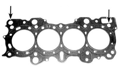
5. Lay a new gasket on the cylinder block (type marking "TOR" up). Make sure that the holes for the guide pins are in their regular places (see accompanying illustration). Reinstall the oil spray head with a new O-ring. Carefully install the cylinder head on the block.
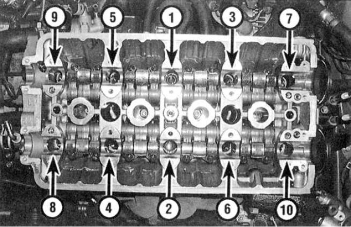
6. Lubricate the threads and the bottom surface of the heads of the mounting bolts with clean engine oil and screw the fasteners into place. Acting in order (see accompanying illustration), tighten the cylinder head bolts to the required torque (see Specifications).
7. Put the gears on the camshaft trunnions, then install the timing belt (see Removal, condition check and installation of camshafts and rocker arm assembly).
8. Install the remaining components in the reverse order of their dismantling.
9. Don't forget to top up the cooling system and check the levels of all fluids (see chapter Current service).
10. Manually turn the crankshaft slowly counterclockwise two full turns.
Attention! If there is resistance when turning the shaft, stop immediately to prevent damage to the valves if they come into contact with the piston crowns.
11. Start the engine and check that the ignition timing is set correctly (see chapter Current service).
12. Warm up the engine to normal operating temperature and check it for signs of leaks. Make sure the engine is working properly.