
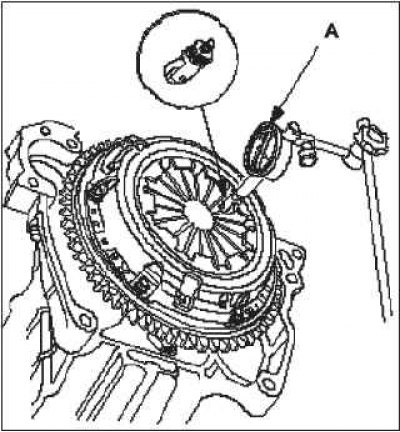
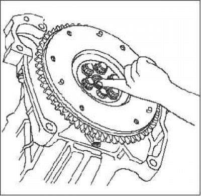
2. Install the special tool.
3. To prevent deformation, unscrew the bolts securing the pressure plate A crosswise in several stages. Then remove the pressure plate.
4. Check the surface of pressure plate A for wear, cracks and signs of overheating.
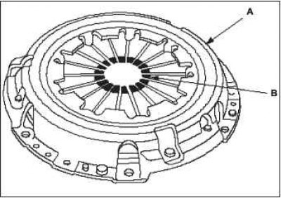
5. Check the petals of the diaphragm spring B for wear in the area of contact with the release bearing.
 |  |
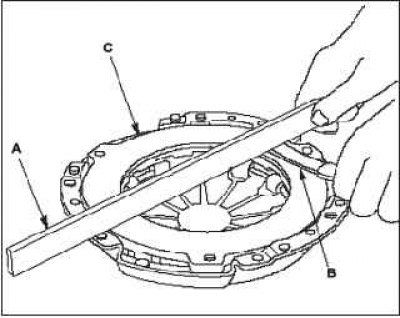
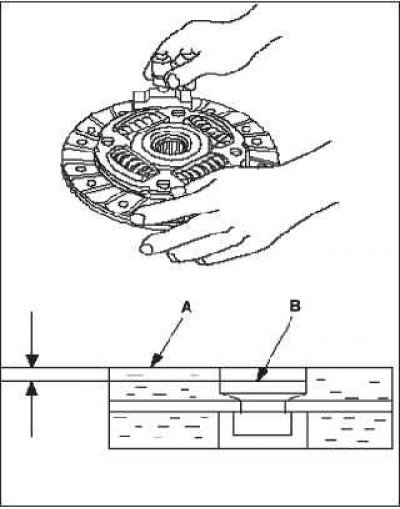
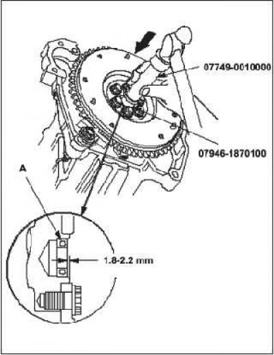
6. Check whether the control ruler A and the calibrated probe B are deformed. Take measurements along the diagonal of the pressure plate C. If the measurement results are out of the working value, replace the pressure plate.
- Standard (new): 0.03 mm.
- Working range: max. 0.15 mm.
7. Remove pressure plate and special tool.
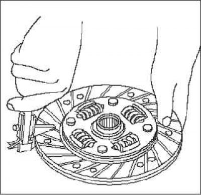
8. Check the clutch friction disc for traces of oil. If the friction disc is blackened from overheating or oily, replace it.
9. Measure the thickness of the friction disc. If the measurement results are out of range, replace the friction disc.
- Standard (new): 7.15-7.85 mm.
- Working range: maximum 5.0 mm.
10. Measure the distance from the friction lining surface A to the rivet heads B on both sides of the disc. If the measurement results are out of range, replace the friction disc.
- Standard (new): 0.9-1.4 mm.
- Working range: maximum 0.2 mm.
 |  |
Guide bearing inspection
1. Turn the pilot bearing inner race with your finger. Rotate the pilot bearing smoothly and quietly. Make sure that the pilot bearing outer race fits snugly against the flywheel. If the ring does not turn smoothly, quietly, or does not fit snugly against the crankshaft, replace the pilot bearing.
Replacing the guide bearing
1. Remove guide bearing A using the special tool.
2. Install the new guide bearing A into the crankshaft using the special tool. Lightly grease the bearing surface.
 |  |
Flywheel check
1. Check the flywheel ring gear for wear and damage.
2. Check the contact surface of the flywheel with the clutch friction disc for wear, cracks and signs of overheating.
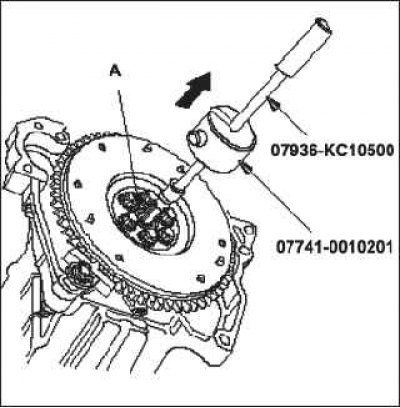
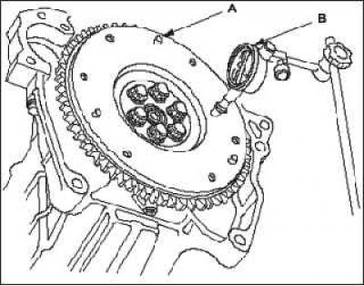
3. Measure the wear of the friction surface A of the flywheel using a dial indicator by turning the flywheel mounted on the engine at least two turns. Apply pressure to the flywheel as it rotates to eliminate the influence of the clearance in the crankshaft bearings on the measurement results. If wear exceeds operating limits, replace flywheel and recheck. Resurfacing of the flywheel surface is not recommended.
- Standard (new): 0.1 mm.
- Working range: max. 0.2 mm.
 |  |
Flywheel replacement
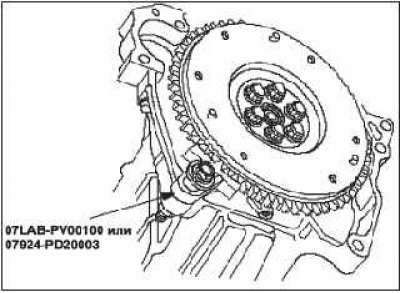
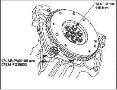
1. Install the special tool.
2. Unscrew the flywheel mounting bolts crosswise in several stages. Then remove the flywheel.
3. Install the flywheel on the crankshaft and install the mounting bolts.
4. Fit the tool and tighten the flywheel mounting bolts in a criss-cross pattern in several steps.
 |  |
Installation of pressure and friction discs
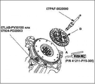
1. Install the ring gear holder.
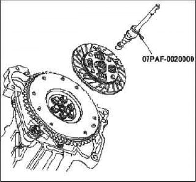
2. Apply grease UM 264 (P/N 41211-PY5—305) on splines A on clutch disc B, then install the clutch disc using the special tools.
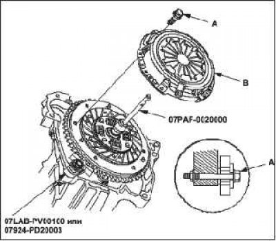
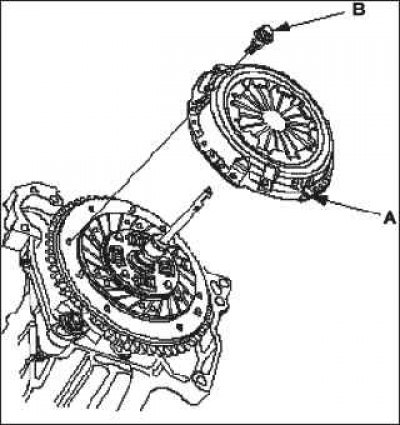
3. Install the pressure plate A and tighten the mounting bolts B.
4. Tighten the mounting bolts crosswise. Tightening should be carried out in several stages to prevent deformation of the diaphragm spring.
5. Remove the special tool.
 |  |
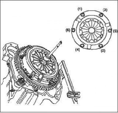
6. Make sure the diaphragm spring tabs are at the same height.