
Note. Make sure the HDS and DLC cables of the HDS system are in order.
1. Turn the ignition key to position «OFF».
2. Connect the HDS to the data port (DLC).
Note. Make sure the HDS is securely connected to the data port (DLC).
3. Turn on the ignition (position II) and look at the HDS indicator. Does the HDS system identify the vehicle?
- YES - go to step 4.
- NO - go to step 23.
4. Check temporary DTCs or PGM-FI system DTCs using HDS. Are temporary DTCs or DTCs output?
- YES - Diagnose the DTCs.
- NO - go to step 5.
5. Turn the ignition key to position «OFF».
6. Turn the ignition key to position «ON» (II) and watch the SRS indicator. Does the SRS indicator stay on?
- YES - Go to General SRS Troubleshooting Information.
- NO - with ABS: go to step 7; with VCA system: go to step 9.
7. Turn the ignition key to position «OFF».
8. Turn the ignition key to position «ON» (II) and watch the ABS indicator. Does the ABS indicator stay on?
- YES - Go to General ABS Troubleshooting Information.
- NO - go to step 11.
9. Turn the ignition key to position «OFF».
10. Turn the ignition key to position «ON» (II) and watch the VSA indicator.
Does the VSA system light stay on?
- YES - Go to General VSA Troubleshooting Information.
- NO - go to step 11.
11. Turn the ignition key to position «OFF».
12. Turn the ignition key to position «ON» (II) and watch the EPS indicator. Does the EPS system indicator stay on?
- YES - Go to EPS System Troubleshooting General Information.
- NO - go to step 13.
13. Turn the ignition key to position «OFF».
14. Turn the ignition switch to position «ON» (II) and watch the immobilizer indicator.
Is the immobilizer indicator on or flashing?
- YES - Go to Immobilizer System Troubleshooting.
- NO - go to step 15.
15. Perform the meter self-test procedure.
16. Check for B-CAN system trouble codes without HDS. Are any B-CAN trouble codes displayed?
- YES - Diagnose the DTCs.
- NO - go to step 17.
17. Turn the ignition key to position «OFF».
18. Disconnect the HDS instrument from the data connector (DLC)
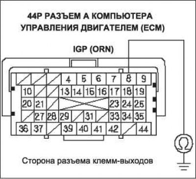
19. Check the continuity between terminal No. 7 of the DLC connector and «weight» body.
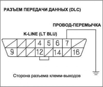
Is the resistance value 5 ohms or less?
- YES - go to step 20.
- NO - go to step 21.
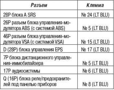
20. Continue checking for continuity between DLC terminal #7 and «weight» body by disconnecting these parts one by one:
- 28P connector A of the SRS unit;
- 26P ABS modulator control unit connector (with ABS system);
- 46P connector of the VSA modulator control unit (with VSA system);
- 28P connector D of the EPS control unit;
- 7P remote control-immobilizer connector;
- 17P audio connector;
- Q connector (16Р) relay/fuse box under the instrument panel.
Does the circuit between the above components break when they are disconnected?
- YES - Replace the part that caused the open circuit when it is disconnected.
- NO - Repair short in wire between DLC (K-line) and ABS modulator control unit (with ABS system), VSA modulator control unit (with VSA system), SRS unit, EPS control unit, remote control immobilizer control unit, audio unit, or under-dash fuse/relay box.
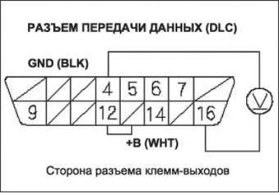
21. Connect terminal No. 7 of the DLC connector to «mass» body with an adapter wire.
22. Check continuity between «body weight» and these connector terminals.
Is there a solid connection between the DLC connector terminal and each of the circuit terminals?
- YES - Replace the unit that cannot communicate with HDS.
- NO - Repair open in the circuit between the DLC connector (K-line) and the corresponding connector.
23. Run the meter self-test procedure.
24. Check for B-CAN system trouble codes without HDS.
Are there messages on the display with codes B1168, B1169 and/or B1178?
- YES - go to step 37.
- NO - go to step 25.
25. Turn the ignition key to position «OFF».
26. Disconnect the HDS instrument from the data connector (DLC)
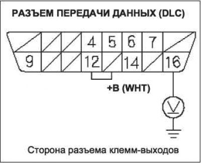
27. Measure the voltage between terminal No. 16 of the DLC connector and «weight» body.
Is there voltage in the battery?
- YES - go to step 28.
- NO - Repair open in the circuit between DLC terminal #16 and fuse #16 +B BACK UP (15 A) in the fuse/relay box in the engine compartment.
28. Measure the voltage between terminals No. 4 and No. 16 of the DLC connector.
Is there battery voltage?
- YES - go to step 29.
- NO - Repair open in the wire between DLC terminal #4 and «weight» body (LRC: G502, with right-hand steering: G503).
29. Connect the HDS instrument to the data port (DLC).
30. Remove the battery.
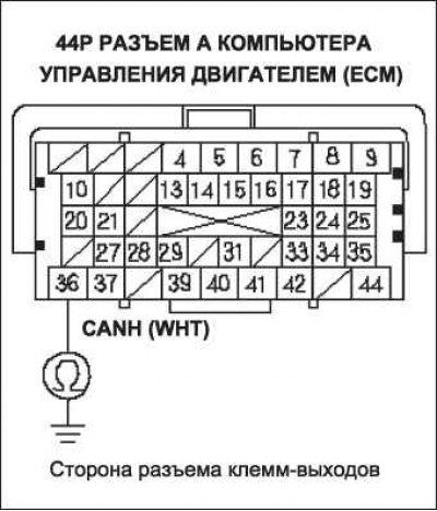
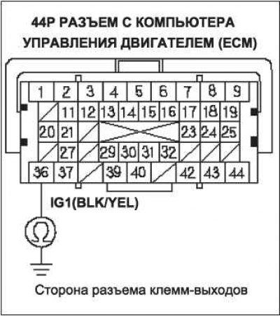
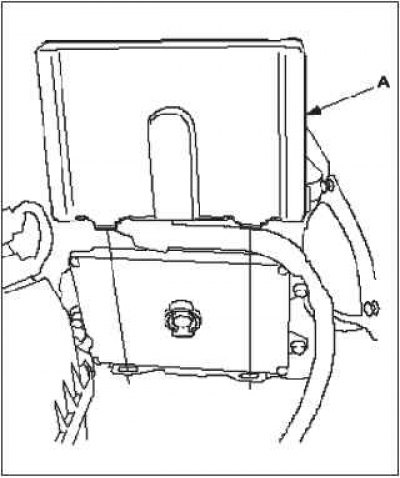
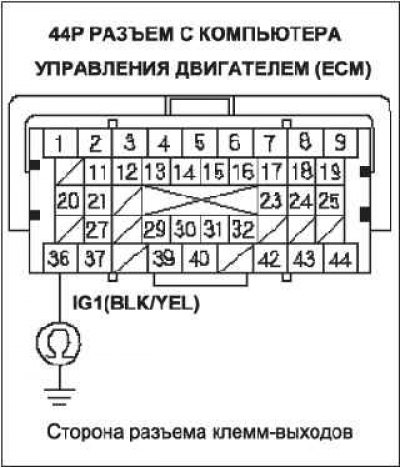
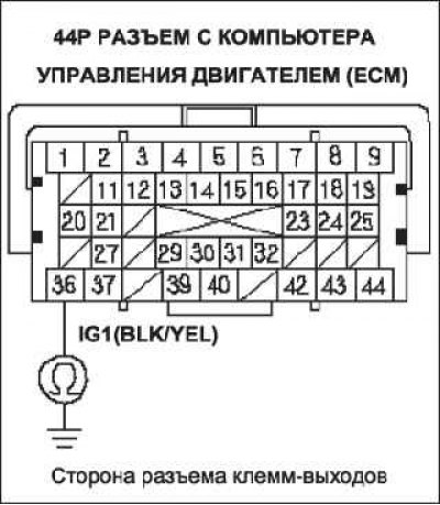
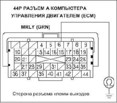
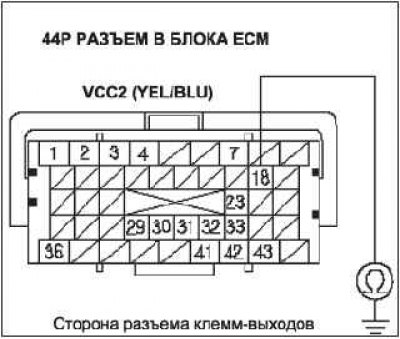
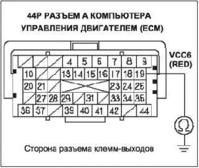
31. Disconnect the 44P connector A of the ECM.
32. Disconnect the HDS instrument from the data connector (DLC)
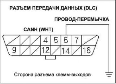
33. Connect terminal No. 6 of the DLC connector to «mass» body with an adapter wire.
34. Check for continuity between ECM connector terminal A36 and «weight» body.
Is the connection continuous?
- YES - go to step 35.
- NO - Repair open in the wire between the ECM (A36) and terminal No. 6 of the DLC connector.
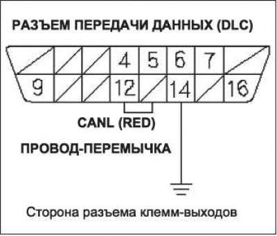
35. Connect terminal No. 14 of the DLC connector to «mass» body with an adapter wire.
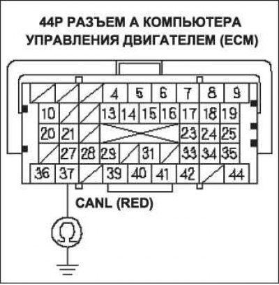
36. Check for continuity between ECM connector terminal A37 and «weight» body.
Is the connection continuous?
- YES - Update the ECM if it does not have the latest software, or temporarily substitute a known-good ECM, then retest. If the problem persists with a known-good ECM, replace the removed ECM.
- NO - Repair open in the wire between the ECM (A37) and terminal No. 14 of the DLC connector.
37. Try to start the engine.
Does the engine start and idle smoothly?
- YES - Go to F-CAN Circuit Troubleshooting.
- NO - go to step 38.
38. Turn the ignition key to position «OFF».
39. Check fuse #2 IG MAIN (50 A) in the relay and fuse box located in the engine compartment.
Is the fuse correct?
- YES - Repair open in the wire between the #2 electrical fuse «IG MAIN» (50 A) and ignition switch. If the wire is OK, go to step 40.
- NO - Repair short between fuse #2 IG MAIN (50 A) and the engine compartment fuse and relay box. Also replace fuse No. 2IG MAIN (50 A).
40. Check fuse number 9 (15 A) in the engine compartment fuse/relay box. Is the fuse correct?
- YES - go to item 45.
- NO - go to step 41.
41. Remove the battery.
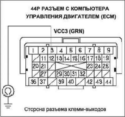
42. Disconnect the 44P connector A of the ECM.
43. Check the continuity of the wire between terminal B6 of the ECM connector and «weight» body.
Is the connection continuous?
- YES - go to step 44.
- NO - Update the ECM if it does not have the latest software, or temporarily substitute a known-good ECM, then retest. If the problem persists with a known-good ECM, replace the removed ECM. Replace No. 9 IGP fuse (15 A).
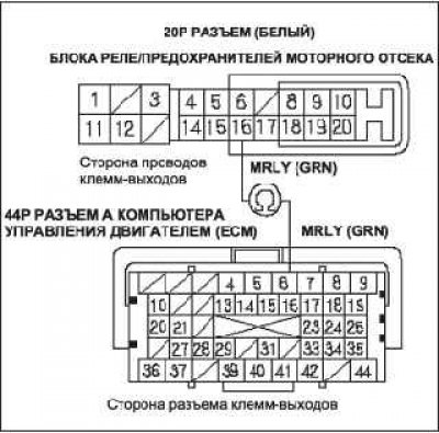
44. Continue checking for continuity between ECM connector terminal A8 and «weight» body, disconnecting these parts one by one:
- main relay 2 PGM-FI modules («FUEL PUMP»);
- 2-pin connector of each injector;
- 3P CKP sensor connector;
- 3P CMP sensor connector;
- 20P connector (white) fuse box / engine compartment relay.
Does the circuit between the above components break when they are disconnected?
- YES - Replace the part that caused the circuit to open when disconnected. Replace No. 9 IGP fuse (15 A).
- NO - Repair open in the wire between the ECM (A8) and main relay 2 PGM-FI (FUEL PUMP), injector, CKP sensor, CMP sensor, or engine compartment fuse/relay box. Replace No. 9 IGP fuse (15 A).
45. Check fuel pump fuse #2 («FUEL PUMP») (15 A) in the fuse/relay box under the control panel.
Is the fuse correct?
- YES - go to 56.
- NO - go to step 46.
46. Remove the battery.
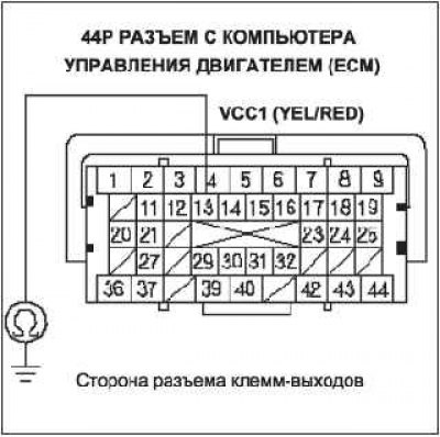
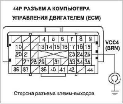
47. Disconnect the 44P connector C from the ECM.
48. Check for continuity in the wire between ECM connector terminal C36 and «weight» body.
Is the connection continuous?
- YES - go to item 49.
- NO - Update the ECM if it does not have the latest software, or temporarily substitute a known-good ECM, then retest. If the problem persists with a known-good ECM, replace the removed ECM. Also replace fuse #2 «FUEL PUMP» (15A).
49. Remove fuel pump A PGM-Fl main relay 2 from under dash fuse/relay box.
50. Check for continuity in the wire between ECM connector terminal C36 and «weight» body.
Is the connection continuous?
- YES - Repair open in the wire between the ECM (C9) and fuse number 2 (15A) fuel pump, between fuse no. 2 (15A) fuel pump and main relay 2 PGM-FI («FUEL PUMP») or between the immobilizer control unit. Also replace the No. 2 FUEL PUMP fuse (15 A).
- NO - go to step 51.
51. Remove access panel A from the floor.
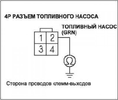
52. Disconnect the 4P connector from the fuel pump.
53. Check for continuity between terminal No. 2 4P of the fuel pump connector and «weight» body.
Is the connection continuous?
- YES - Repair short in the wire between the fuel pump and PGM-FI main relay 2 («FUEL PUMP»). Also replace fuse #2 «FUEL PUMP» (15A).
- NO - go to step 54.
54. Reinstall main relay 2 of fuel pump A PGM-Fl into the under dash fuse/relay box.
55. Check for continuity between terminal No. 2 4P of the fuel pump connector and «weight» body.
Is the connection continuous?
- YES - Replace PGM-FI Main Relay 2 («FUEL PUMP»). Also replace fuse #2 «FUEL PUMP» (15 A).
- NO - Check the fuel pump and replace if necessary. Also replace the No. 2 FUEL PUMP fuse (15 A).
56. Remove the battery.
57. Disconnect the 44P connectors A and C of the ECM
58. Connect the battery.
59. Turn on the ignition by turning the key to position «ON» (II).
60. Measure voltage between ECM connector terminal C36 and «weight» body.
Is there voltage in the battery?
- YES - go to 61.
- NO - Repair open in the wire between the ECM (C36) and fuel pump fuse No. 2 (15 A).
61. Measure the voltage between terminal A6 of the ECM connector and «weight» body.
Is there battery voltage?
- YES - go to 66.
- NO - go to step 62.
62. Turn the ignition key to position «OFF».
63. Disconnect the battery.
64. Disconnect 20P (white) fuse/relay box connector in the engine compartment.
65. Check continuity between terminal A6 of the ECM connector and terminal No. 16 20P (white) fuse/relay box connector.

Is the connection continuous?
- YES - Replace the engine compartment relay/fuse box. Update the ECM if it does not have the latest software, or temporarily substitute a known-good ECM, then recheck. If the problem persists with a known-good ECM, replace the removed ECM.
- NO - Repair open in the wire between the ECM (A6) and the engine compartment fuse/relay box.
66. Turn the ignition key to position «OFF».
67. Disconnect the battery.
68. Disconnect 20P (white) fuse/relay box connector in the engine compartment.
69. Check continuity between ECM connector terminal A8 and terminal No. 5 20P (white) fuse/relay box connector.
Is the connection continuous?
- YES - go to item 70.
- NO - Repair open in the wire between the ECM (A6) and the engine compartment fuse/relay box.
70. Check PGM-F main relay 1.
Is PGM-FI main relay 1 OK?
- YES - go to 71.
- NO - Replace the relay/fuse box in the engine compartment.
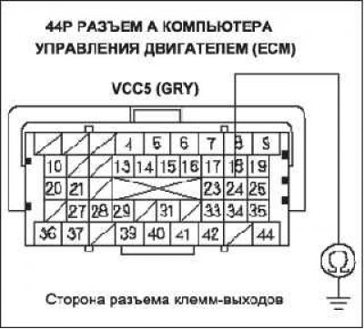
71. Disconnect the 44P connector B of the ECM.
72. Check the continuity of the connection between «weight» body and terminals B1, B36, C2, C40 and C44 of the ECM connector separately.
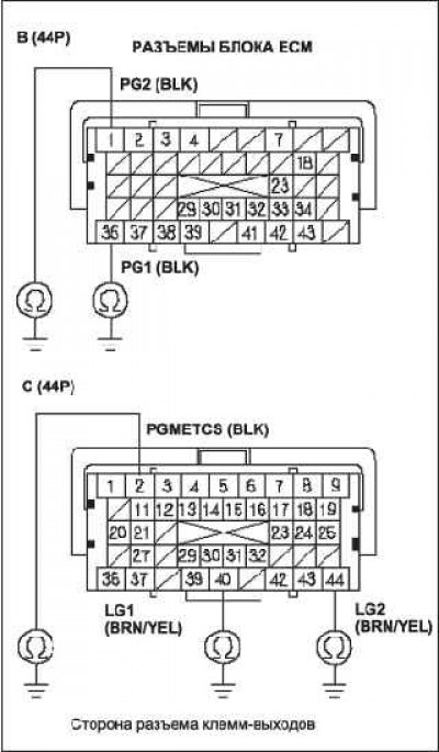
Is the connection continuous?
- YES - go to 73.
- NO - Repair open in the wire between the ECM (B1, B36, C2, C40, C44) And «weight» GlOl.
73. Check for continuity in the wire between ECM connector terminal C13 and «weight» body.
Connector side of output terminals
Is the connection continuous?
- YES - go to 74.
- NO - go to item 75.
74. Continue to check continuity between ECM connector terminal C13 and «weight» body, disconnecting these parts one by one:
- 3P MAP sensor connector;
- 3P connector crankshaft speed sensor;
Does the circuit between the above components break when they are disconnected?
- YES - Replace the part that caused the open circuit when it is disconnected.
- NO - Repair open in the wire between the ECM (C13) and MAP sensor, crankshaft speed sensor.
75. Check the continuity of the wire between terminal B18 of the ECM connector and «weight» body.
Is the connection continuous?
- YES - go to 76.
- NO - go to item 77.
76. Continue to check continuity between ECM/PCM connector terminal B18 and «weight» body by disconnecting the 6P EGR valve connector.
Is the connection continuous?
- YES - Repair short between ECM (B 18) and EGR valve.
- NO - Replace the EGR valve.
77. Check for continuity in the wire between ECM connector terminal C12 and «weight» body.
Is the connection continuous?
- YES - go to 78.
- NO - go to item 79.
78. Continue to check continuity between ECM connector terminal C12 and «weight» body by disconnecting the 6P throttle body connector.
Is the connection continuous?
- YES - Repair open in the wire between the ECM (C 12) and throttle body
- NO - Replace the throttle body.
79. Check continuity between ECM connector terminal A25 and «weight» body.
Is the connection continuous?
- YES - go to 80.
- NO - go to 81.
80. Continue to check continuity between ECM connector terminal A25 and «weight» body by disconnecting the APP sensor 6P connector.
Is the connection continuous?
- YES - Repair open in the wire between the ECM (A25) and APP sensor A.
- NO - Replace the accelerator pedal module.
81. Check continuity between ECM connector terminal A24 and «weight» body.
Is the connection continuous?
- YES - go to 82.
- NO - go to 83.
82. Continue checking for continuity between ECM connector terminal A24 and «weight» body by disconnecting the APP sensor 6P connector.
Is the connection continuous?
- YES - Repair open in the wire between the ECM (A24) and sensor B APP.
- NO - Replace the accelerator pedal module.
83. Check the continuity of the wire between terminal A19 of the ECM connector and «weight» body.
Is the connection continuous?
- YES - go to 84.
- NO - Update the ECM if it does not have the latest software, or temporarily substitute a known-good ECM, then retest. If the problem persists with a known-good ECM, replace the removed ECM.
84. Continue checking for continuity between ECM connector terminal A19 and «weight» body by disconnecting the A/C pressure sensor 3P connector.
Is the connection continuous?
- YES - Repair short in the wire between the ECM/PCM (A19) and air conditioner pressure sensor.
- NO - Replace A/C pressure sensor.