
2. Locate the heater fan motor relay in the mounting block in the engine compartment of the vehicle. Remove this relay and check its proper functioning (see Chapter On-board electrical equipment). Replace the faulty relay.
3. Shift the transmission into position "P", set the parking brake and turn the ignition key to the ON position without starting the engine.
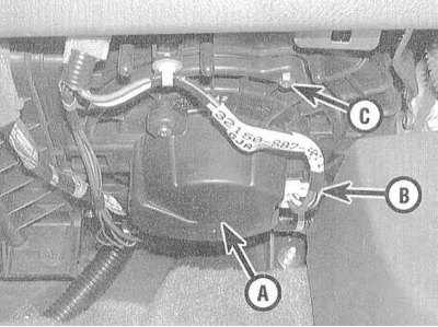
4. The heater fan assembly is located under the vehicle's instrument panel, behind the glove compartment, near the engine compartment bulkhead.
5. Set the air supply direction control handle on the heater control panel to the FLOOR position, set the fan speed mode selection handle to position 4. Try to determine by ear whether air is supplied through the air ducts. If air is supplied, set the speed mode handle to position 1 and listen again. Repeat the check in each of the handle positions.
Note: The fan speed switch is included in the electric motor circuit on the ground side.
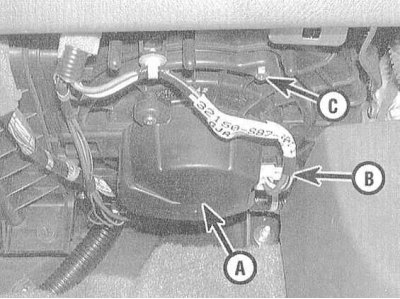
6. If the fan does not operate and all fuses and relays have been checked and are in good condition, it is time to check the electric motor itself. Locate the electrical connector on the back of the fan assembly and use a sharp probe of a voltmeter to probe the yellow/black wire terminal with the ignition on. There should be at least 10 volts at this terminal with the speed switch in any position except the OFF position, otherwise there is a fault in the circuit between the fuse box and the heater/air conditioning control panel, or between the control panel and the electric motor.
7. If there is voltage on the power supply, but the fan does not work, short the terminal of the blue-red wire to the chassis ground (use a jumper wire with a sharp probe). If the fan does not work when the terminal is grounded, replace the electric motor of its drive, otherwise you should check the condition of the circuit in the section between the speed mode selection switch and the resistor assembly.
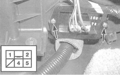
8. If the fan only works in some of the speed modes, check its resistor. The resistor assembly is attached to the fan casing on the right under the instrument panel. There are three resistors on the board, which provide the ability to operate the fan in three lower different speed modes; when the fan is turned on at maximum speed (position 4), the current is passed through the resistor bypass device.
9. Remove the resistor assembly and visually assess the condition of its elements (the elements should not be melted). Measure the resistance between terminals 1 and 5 of the connector. If the measurement result is outside the range of 5÷3.5 Ohm, replace the assembly.
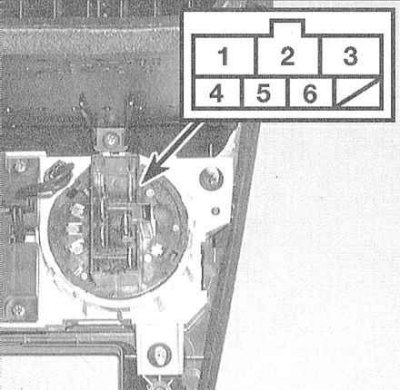
10. If the resistor assembly is OK, but the fan still does not operate at all speeds, you should refer to the materials in Section On-board electrical equipment and remove the heater/air conditioner control panel. Disconnect the wiring connector from the back of the fan speed selector switch and check the distribution of conductivity between the contact terminals in the different switch positions. A faulty switch must be replaced.
 |
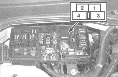 |
11. Check the condition of the heater fan relay in the mounting block in the engine compartment of the vehicle. Remove the relay from its socket and check its proper functioning (see Chapter On-board electrical equipment). Use a voltmeter to probe the contact terminals in the mounting block socket: battery voltage should be present at terminal 4 all the time, and at terminal 1 only when the ignition is on. Terminal 2 should be grounded to ground at all times.
The article was copied from the website HondaBook.ru