
HondaBook.ru
Auto companies Volkswagen Auto companies Ford Auto companies Lada Auto companies Skoda Auto companies BMW Auto companies Mazda Auto companies Peugeot
English Русский
Български
Беларускі
Український
Српски
Hrvatski
Română
Polski
Slovenský
Magyar
Bookmark Contacts Sitemap   


Accord Civic Fit / Jazz CR-V HR-V Others Articles
Civic 3 and 4 (1983-1991) Civic 5 and 6 (1991-2000) Civic 6 (1995-2000) Civic 7 (2000-2005) Civic 8 (2005-2011)

Troubleshooting the Fuel Pump Circuit (L13A) (Honda Civic 8)

  • Main
  • Honda Civic
  • 8 (2005-2011)
  • Power unit
  • Injection system (gasoline)
  • Troubleshooting the Fuel Pump Circuit (L13A)
0
Note: If you suspect any fault with the fuel pump, first make sure that it is working. To do this, remove the fuel filler cap and listen: if the pump is working, you will hear a characteristic sound. The fuel pump should work within 2 seconds after the ignition is first turned on. If you do not hear the sound of the fuel pump working, check the following:


1. Turn the ignition key to the "OFF" position.

2. Remove the under-dash fuse/relay box, then remove the PGM-Fl module main relay 2 (FUEL PUMP) And from the electrical relay/fuse block under the control panel.
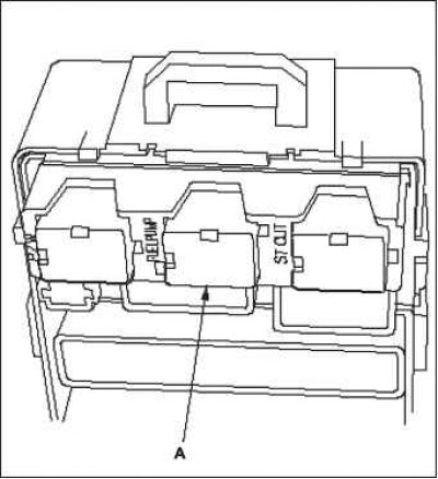
3. Reinstall the relay/fuse box under the…


3. Reinstall the relay/fuse box under the dashboard.

4. Turn the ignition on by turning the key to the "ON" (II) position.

5. Measure the voltage between terminal No.3 of the 4-pin connector of the main relay 2 of the PGM-Fl module "FUEL PUMP" (FUEL PUMP) and the "mass" of the body.
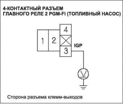
Is there voltage in the battery?


Is there voltage in the battery?


  • YES - Proceed to step 10.
  • NO - Proceed to step 6.

6. Turn the ignition key to the "OFF" position.

7. Disconnect the 20P connector from the engine compartment fuse/relay box.

8. Turn the ignition on by turning the key to the "ON" (II) position.

9. Measure the voltage between terminal No.5 of the 20P engine compartment fuse/relay box connector and body ground.
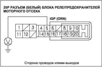
Is there voltage in the battery?


Is there voltage in the battery?
  • YES - Repair open in wire between engine compartment fuse/relay box and under-dash fuse/relay box.
  • NO - Replace PGM-FI Main Relay 1.

Replace the engine compartment fuse/relay box if necessary.

10. Measure the voltage between terminal No.1 of the 4-pin connector of the main relay 2 of the PGM-FL module
  • YES - go to step 16.
  • NO - go to step 11.

11. Turn the ignition key to the "OFF" position.

12. Disconnect the 3-pin inertia switch connector.

13. Connect terminals No.1 and No.3 of the 3-pin radiator cooling fan switch connector with a jumper wire.

14. Turn the ignition on by turning the key to the "ON" (II) position.

15. Measure the voltage between terminal No.1 of the 4-pin connector of the main relay 2 of the PGM-Fl module "FUEL PUMP" (FUEL PUMP) and the "mass" of the body.
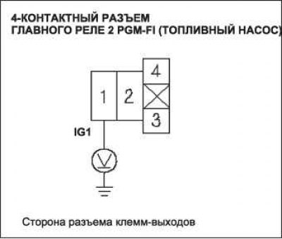


Is there voltage in the battery?


Is there voltage in the battery?
  • YES - replace the inertia switch.
  • NO-Replace fuse # 2 of the IG1 FUEL PUMP (15 A) in the fuse box/relay assembly located under the control panel.

Replace the under-dash fuse/relay box.

Repair open in wire between inertia switch and under-dash fuse/relay box.

16. Turn the ignition key to the "OFF" position.

17. Connect terminal No.4 of the 4-pin connector of the main relay 2 of the PGM-Fl module "FUEL PUMP" (FUEL PUMP) and the body ground using a jumper wire.

18. Bypass the SCS circuit with the HDS diagnostic system.

19. Disconnect the 44P connector A of the ECM unit.

20. Check for continuity between ECM connector terminal A15 and body ground.

Is the connection continuous?
  • YES - go to step 21.
  • NO - Repair open in wire between PGM-Fl module main relay 2 "FUEL PUMP" (FUEL PUMP) and the ECM unit (A15).

21. Remove the under-dash fuse/relay box, then reinstall the PGM-FI Main Relay 2 (FUEL PUMP).

22. Reinstall the under-dash fuse/relay box.

23. Connect terminal A6 of the ECM connector to the body ground using a jumper wire.

24. Turn the ignition on by turning the key to the "ON" (II) position.


25. Measure the voltage between terminal A15 of the ECM connector and body ground.

Is there voltage in the battery?
  • YES - go to step 26.
  • NO - Replace PGM-FI(FUEL PUMP) module main relay 2.

26. Turn the ignition key to the "OFF" position.

27. Reconnect the 44P connector A of the ECM unit.

28. Open the SCS circuit using the HDS.

29. Turn the ignition key to the "OFF" position.

30. Turn the ignition switch to the ON (II) position and measure the voltage between terminal No.10 of the under-dash fuse/relay box 34P connector and body ground for 2 seconds.
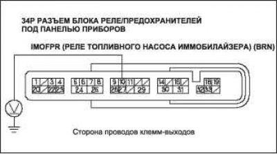
Is there voltage in the battery?


Is there voltage in the battery?
  • YES - Update the ECM if it does not have the latest software, or temporarily replace it with a known good ECM, then retest. If the fault does not occur with a known good ECM, replace the original ECM, then go to step 31.
  • NO - If necessary, replace the under-dash fuse/relay box, then go to step 31.

31. Turn the ignition key to the "OFF" position.

32. Remove access panel A from the floor.

33. Turn the ignition switch to the ON (II) position and measure the voltage between terminal No.2 of the fuel tank block 4P connector and body ground for 2 seconds.


Is there voltage in the battery?
  • YES - go to step 38.
  • NO - go to step 34.

34. Turn the ignition key to the "OFF" position.

35. Remove the main relay 2 of the PGM-FI module "FUEL PUMP" (FUEL PUMP).

36. Connect terminals No.1 and No.2 of the 4-pin connector of the main relay 2 of the PGM-Fl module "FUEL PUMP" (FUEL PUMP) using a jumper wire.
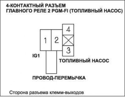
37. Turn the ignition switch to the «ON» (II)…


37. Turn the ignition switch to the "ON" (II) position and measure the voltage between terminal No.2 of the fuel tank block 4P connector and body ground for 2 seconds.

Is there voltage in the battery?
  • YES - Replace PGM-FI(FUEL PUMP) module main relay 2.
  • NO - Repair open in the wire between the PGM-Fl module main relay 2 (FUEL PUMP) and the 4P connector of the fuel tank unit.

38. Turn the ignition key to the "OFF" position.

39. Check for continuity between terminal No.4 of the 4P fuel tank connector and body ground.
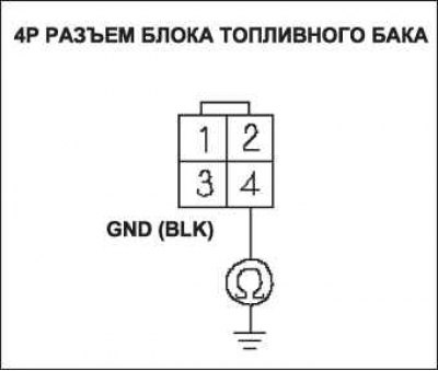
Is the connection continuous?


Is the connection continuous?
  • YES - replace the fuel pump.
  • NO - Repair open in wire between fuel tank 4P connector and G601.
This article is available at: russian, bulgarian, belarusian, ukrainian, serbian, croatian, romanian, polish, slovak, hungarian
This information has been verified: Yaroslav Shiryaev
Share with friends:
◀ Previous
Civic 8: Injection system (gasoline)
Next ▶

Replacing the fuel level indicator transmitter (L13A)
Replacing the fuel pressure regulator (L13A)
Installation of fuel line connectors for the fuel system (L13A)
Removal the fuel line connectors of the fuel system (L13A)
Checking the fuel level indicator transmitter (L13A)
Removal and installation the fuel tank (L13A)
Replacing the inertia switch (L13A)
See also other articles from Honda manuals:
Fuel pump — testing Honda Accord 3 (1985-1989)
Fuel pump Honda Fit 1 (2001-2008)
Fuel pump, horn and cooling fan diagram Honda CR-V 1 (1995-2001, petrol)
Fuel pump — testing Honda HR-V 1 (1998-2006, petrol)
Checking the fuel pump Honda Avancier 1 (1999-2003, petrol)
Link in different formats to this article
Comments and feedback from visitors
No comments yet


How much will 40 + 11 ?


Civic 8 (2005-2011) 
  • General information
  • Technical data
  • Governing bodies
  • Driving and maintenance
  • Power unit
  • Gasoline engines (L13A)
  • Gasoline engines (R18A)
  • Diesel engines (N22A)
  • Cooling and lubrication (L13A)
  • Cooling and lubrication (R18A)
  • Cooling and lubrication (N22A)
  • Injection system (gasoline)
  • Injection system (diesel)
  • Toxicity reduction system
  • Troubleshooting
  • Transmission
  • Clutch and drive shafts
  • Mechanical gearbox
  • Chassis and running gear
  • Suspension and wheels
  • Steering
  • Brake system
  • Body and interior
  • Exterior (external elements)
  • Doors, locks and windows
  • Electrical equipment
  • Equipment and devices
  • Headlights and lighting
  • Power devices
  • Electrical circuits
Civic 7 (2000-2005) 
  • General information
  • User manual
  • Maintenance
  • Power unit
  • Engines D15B and D17A
  • K20A Engines
  • Overhaul engine
  • Cooling system
  • Lubrication system
  • Fuel injection system
  • Toxicity reduction system
  • Engine electrical equipment
  • Transmission
  • Clutch
  • Manual gearbox
  • Automatic gearbox
  • Variator (CVT)
  • Drive shafts
  • Chassis and running gear
  • Car suspension
  • Steering
  • Brake system
  • Body and interior
  • Exterior (external elements)
  • Interior (internal elements)
  • Doors, locks and windows
  • Heater and air conditioner
  • Manual air conditioner
  • Automatic air conditioner
  • Security system
  • Electrical equipment
  • Equipment and devices
  • Headlights and lighting
  • Windscreen wipers
  • Audio system
  • Electrical diagrams
Civic 6 (1995-2000) 
  • General information
  • Introduction to guide
  • User manual
  • Maintenance
  • Power unit
  • Engine in car (Civic)
  • Engine in car (Integra)
  • Engine overhaul
  • Cooling and heating
  • Power and exhaust systems
  • Engine electrical equipment
  • Engine management systems
  • Transmission
  • Manual gearbox
  • Automatic transmission (AT/CVT)
  • Clutch and drive shafts
  • Chassis and running gear
  • Brake system
  • Car suspension
  • Steering
  • Body and interior
  • Exterior (external elements)
  • Interior (internal elements)
  • Doors, locks and windows
  • Electrical equipment
  • Equipment and devices
  • Electrical circuits
Civic 5 and 6 (1991-2000) 
  • Power unit
  • SOHC engines
  • DOHC engines
  • Engine overhaul
  • Cooling and lubrication system
  • Intake and exhaust system
  • Fuel injection system (SOHC)
  • Fuel injection system (DOHC)
  • Carburetor
  • Transmission
  • Clutch
  • Manual gearbox S4C
  • Manual gearbox S40
  • Automatic gearbox
  • Drive shafts
  • Chassis and running gear
  • Car suspension
  • Steering
  • Brake system
  • Body and interior
  • Body elements
  • Heater and air conditioner
  • Electrical equipment
  • Power devices
  • Equipment and instruments
  • Electrical circuits
Civic 3 and 4 (1983-1991) 
  • General information
  • Maintenance
  • Power unit
  • Engine in a car
  • Engine overhaul
  • Cooling system
  • Power and exhaust system
  • Engine electrical equipment
  • Emission control system
  • Transmission
  • Mechanical gearbox
  • Automatic gearbox
  • Clutch and drive shafts
  • Four-wheel drive
  • Chassis and running gear
  • Brake system
  • Car suspension
  • Steering
  • Body and interior
  • Body elements
  • Electrical equipment
  • Equipment and devices
  • Electrical circuits
HondaBook.ru © 2018–2026 • Mobile version • Sitemap: EN BG BY UA RS HR RO PL SK HU • Feedback • Driver Information • Search system • Bookmark
Accord 3 (1985-1989) • Accord 6 (1997-2002) • Civic 3 and 4 (1983-1991) • Civic 5 and 6 (1991-2000) • Civic 6 (1995-2000) • Civic 7 (2000-2005) • Civic 8 (2005-2011) • Fit 1 (2001-2008) • CR-V 1 (1995-2001) • CR-V 2 (2002-2006) • HR-V 1 (1998-2006) • Avancier 1 (1999-2003) •
 
This website uses cookies to ensure proper functioning. By clicking "OK," you agree.