
Contents: Reading diagnostic codes using a…⇊ Reading diagnostic codes using a…⇊ Resetting fault codes ⇊ Control unit training procedure ⇊
Reading diagnostic codes using a special tool
1. Turn the ignition switch to the "OFF" position.
2. Connect the special tool to the diagnostic connector.
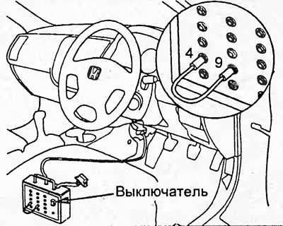
3. Install a jumper between terminals "4" and "9" of the special device.
4. Turn on the ignition. The indicator will start flashing, displaying fault codes (see the figure "Fault codes").
5. Read and write down the fault codes. Using the "Fault Codes" table, determine and eliminate the cause of the fault.
Note:
- Error codes with numbers up to 10 are displayed by a series of short flashes. The number of flashes corresponds to the code number.
- Error codes with numbers 10 and higher are displayed in two series of flashes. The first digit of the code is determined by the initial series of long flashes, then, after a pause, a second series of short flashes follows, which corresponds to the second digit of the code.
- If there are two or more fault codes, the lowest code will be displayed first, followed by the remaining codes in ascending order.
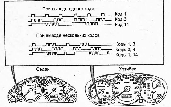
Error codes.
6. After troubleshooting, clear the fault codes (see the subsection "Resetting fault codes").
7. Turn off the ignition, remove the jumper and disconnect the special tool from the diagnostic connector.
Reading diagnostic codes using a scanner
1. Turn the ignition switch to the "OFF" position.
2. Connect the scanner to the diagnostic connector.
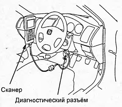
3. Turn on the ignition. Read the fault codes.
Resetting fault codes
Using a scanner
1. Turn the ignition switch to the "OFF" position.
2. Connect the scanner.
3. Turn the ignition switch to the "ON" position.
4. Clear fault codes.
Without using a scanner
1. Turn the ignition switch to the "OFF" position.
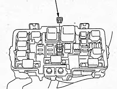
2. Remove fuse #6 (ECU/PCM) (15A) from the relay/fuse box for more than 10 seconds.
Control unit training procedure
Perform the control unit learning procedure after performing the following operations:
- Disconnecting the wire from the negative terminal of the battery;
- Replacing the control unit or disconnecting the connector;
- Resetting control unit data;
Note: After deleting diagnostic codes using a scanner, this procedure does not need to be performed.
- Removal fuse #6 (ECU) (15A) from the relay/fuse box;
- Removal fuse #19 (80A) from the relay/fuse box;
- Removal Main Relay #1;
- Disconnecting the wiring harness from the relay/fuse box;
- Disconnecting any control system components from the wiring harness;
- Disconnecting ground wires from the automatic transmission, engine, and body.
1. Turn off all consumers (air conditioning, radio, rear door glass heater, etc.)
2. Start the engine and set the crankshaft speed to 3000 rpm. Wait until the cooling system fan turns on or the coolant temperature reaches 90°C.
3. Let the engine run for 5 minutes with the throttle fully closed.
Note: When turning on the cooling fan, stop the stopwatch and turn it on again after the fan turns off.
Table. Diagnostic trouble codes (d series engines).
| Honda tester code | SAE code | System or sensor |
| 0-2 | R1607 | Control unit |
| 0-29 | R1607 | Control unit |
| 1-1 | P0131 | Low signal from the oxygen sensor before the catalytic converter |
| 1-2 | P0132 | High signal oxygen sensor before catalytic converter |
| 3-1 | P0107 | Low signal from the intake manifold vacuum sensor |
| 3-2 | P0108 | Intake Manifold Vacuum Sensor High Signal |
| 4-1 | P0335 | No signal from crankshaft position sensor |
| 4-2 | P0336 | Incorrect crankshaft position sensor signal |
| 4-6 | P0339 | Poor contact of the crankshaft position sensor electrical circuit |
| 6-1 | P0117 | Coolant Temperature Sensor Low Signal |
| 6-2 | P0118 | Coolant Temperature Sensor High Signal |
| 7-1 | P0122 | Throttle Position Sensor Low Signal |
| 7-2 | P0123 | Throttle Position Sensor High Signal |
| 8-1 | R1362 | Low signal from the camshaft position sensor |
| 8-5 | P0340 | Camshaft Position Sensor Electrical Circuit Malfunction |
| 8-2 | R1361 | High signal from the camshaft position sensor |
| 8-7 | P0344 | Poor contact of the electrical circuit of the camshaft position sensor |
| 10-1 | P0112 | Low Intake Air Temperature Sensor Signal |
| 10-2 | P0113 | Intake Air Temperature Sensor High Signal |
| 12-2 | R1498 | EGR Valve High Signal |
| 12-5 | P0406 | EGR Valve High Signal |
| 12-3 | R1491 | EGR valve wiring harness break |
| 12-4 | P0404 | EGR valve wiring harness break |
| 13-1 | R1107 | Low signal from the intake manifold vacuum sensor |
| 13-5 | R2228 | Low signal from the intake manifold vacuum sensor |
| 13-2 | R1108 | Intake Manifold Vacuum Sensor High Signal |
| 13-6 | R2229 | Intake Manifold Vacuum Sensor High Signal |
| 14-3 | R1519 | Valve of the idle speed control system |
| 14-12 | P0511 | Valve of the idle speed control system |
| 17-1 | P0500 | No vehicle speed sensor signal |
| 17-2 | P0501 | No vehicle speed sensor signal |
| 20-1 | R1297 | Low signal from the power supply voltage monitoring system unit |
| 20-2 | R1298 | High signal from the power supply voltage monitoring system unit |
| 21-1 | R1253 | Variable Valve Timing and Elevation Control (VTEC) |
| 21-4 | R2645 | Variable Valve Timing and Elevation Control (VTEC) |
| 23-1 | P0325 | Knock sensor wiring harness break |
| 23-2 | R1324 | Incorrect knock sensor signal |
| 34-2 | P0563 | Control unit supply voltage |
| 39-1 | P0600 | Multiplex data bus |
| 41-1 | R1166 | Air-fuel ratio sensor heater wiring harness break |
| 41-2 | P0135 | Open in the wiring harness of the oxygen sensor heater before the catalytic converter |
| 41-2 | P0135 | Air-fuel ratio sensor heater wiring harness break |
| 41-2 | P0135 | Open in the wiring harness of the oxygen sensor heater before the catalytic converter |
| 41-4 | R1167 | Air-fuel ratio sensor heater wiring harness break |
| 41-5 | P0135 | Air-fuel ratio sensor heater wiring harness break |
| 41-7 | P0134 | Air-fuel ratio sensor heater wiring harness break |
| 45-1 | P0172 | Clogged intake system, electropneumatic valve of the fuel vapor capture system, fuel pressure, exhaust gas recirculation system (EGR), nozzle, heated oxygen sensor |
| 45-2 | P0171 | Intake/Exhaust Leak, Secondary Air Injection System, Mass Air Flow Sensor, Fuel Pressure/Fuel Pump, Injector, Heated Oxygen Sensor |
| 48-3 | R1162 | Oxygen sensor |
| 48-5 | R1157 | Mixture Composition Sensor (LAF) |
| 48-17 | R2252 | Low Air-Fuel Ratio (LAF) Sensor Signal (-) |
| 48-18 | R2238 | Low Air-Fuel Ratio (LAF) Sensor Signal (+) |
| 63-1 | P0137 | Heated Oxygen Sensor After Catalytic Converter Low Signal |
| 63-2 | P0138 | Heated Oxygen Sensor After Catalytic Converter High Signal |
| 63-3 | P0139 | Damage to the oxygen sensor after the catalytic converter |
| 65-2 | P0141 | Oxygen sensor heater wiring harness broken after catalytic converter |
| 70-2 | - | Automatic transmission |
| 71-3 | - | Automatic transmission |
| 71-1 | P0301 | Cylinder 1 - misfire |
| 72-1 | P0302 | Cylinder 2 - misfire |
| 73-1 | P0303 | Cylinder 3 - misfire |
| 74-1 | P0304 | Cylinder 4 - misfire |
Table. Diagnostic trouble codes (engine K20A).
| Indicator flashing | SAE code | System or sensor |
| 56 | P0010 | Variable Valve Timing (VTC) Valve |
| 56 | P0011 | Variable Valve Timing (VTC) |
| 3 | P0107 | Low signal from the intake manifold vacuum sensor |
| 3 | P0108 | Intake Manifold Vacuum Sensor High Signal |
| 10 | P0112 | Intake Air Temperature Sensor Low Signal |
| 10 | P0113 | Intake Air Temperature Sensor High Signal |
| 86 | P0116 | Coolant temperature sensor |
| 6 | P0117 | Low Coolant Temperature Sensor Signal |
| 6 | P0118 | Coolant Temperature Sensor High Signal |
| 7 | P0122 | Throttle Position Sensor Low Signal |
| 7 | P0123 | Throttle Position Sensor High Signal |
| 87 | P0128 | Cooling system |
| 41 | P0134 | Air-Fuel Composition Sensor - No Response |
| 63 | P0137 | Heated Oxygen Sensor After Catalytic Converter Low Signal |
| 63 | P0138 | Heated Oxygen Sensor After Catalytic Converter High Signal |
| 63 | P0139 | Damage to the oxygen sensor after the catalytic converter |
| 65 | P0141 | Oxygen sensor heater wiring harness broken after catalytic converter |
| 45 | P0171 | Poor fuel mixture Leaky intake / exhaust system, exhaust air supply system, mass flow sensor, fuel pressure / fuel pump. nozzle, heated oxygen sensor |
| 45 | P0172 | Rich fuel mix Clogging of the intake system, electropneumatic valve of the fuel vapor capture system, fuel pressure, exhaust gas recirculation system (EGR), nozzle. heated oxygen sensor |
| 71 | P0301 | Cylinder 1 - misfire |
| 72 | P0302 | Cylinder 2 - misfire |
| 73 | P0303 - | Cylinder 3 - misfire |
| 74 | P0304 | Cylinder 4 - misfire |
| 71,72, 73, 74 | P0300 | Multiple misfires |
| 23 | P0325 | Knock sensor wiring harness break |
| 4 | P0335 | No signal from crankshaft position sensor |
| 4 | P0336 | Incorrect crankshaft position sensor signal |
| 57 | P0340 | Camshaft Position Sensor Electrical Circuit Malfunction |
| 57 | P0341 | Camshaft Position Sensor |
| 57 | P0344 | Poor contact of the electrical circuit of the camshaft position sensor |
| 67 | P0420 | Low efficiency of the catalytic converter |
| 97 | P0451 | Fuel Evaporative Emission System Pressure Sensor |
| 97 | P0452 | Fuel Evaporative Emission System Pressure Sensor Low Signal |
| 97 | P0453 | Fuel Evaporative Emission System Pressure Sensor High Signal |
| 17 | P0500 | No vehicle speed sensor signal |
| 14 | P0505 | Idle Speed Control System - Malfunction |
| 34 | P0563 | Control unit supply voltage |
| 39 | . P0600 | Multiplex system circuit failure |
| 13 | R1106 | Absolute pressure sensor |
| 13 | R1107 | Low Absolute Pressure Sensor Signal |
| 13 | R1108 | Absolute pressure sensor high signal |
| 7 | R1121 | Throttle position sensor signal is below the calculated value |
| 7 | R1122 | Throttle position sensor signal is higher than expected |
| 5 | R1128 | Absolute pressure sensor signal is lower than calculated |
| 5 | R1129 | Absolute pressure sensor signal is higher than calculated |
| 48 | R1157 | Mixture Composition Sensor (LAF) |
| 48 | R1158 | Low signal air-fuel ratio sensor (LAF) |
| 48 | R1159 | High Air-Fuel Ratio (LAF) Sensor Signal |
| 41 | R1166 | Mixture Composition Sensor (LAF) |
| 41 | R1167 | Mixture Composition Sensor (LAF) |
| 22 | R1259 | Variable Valve Timing and Elevation Control (VTEC) |
| 20 | R1297 | Low signal from the power supply voltage monitoring system unit |
| 20 | R1298 | High signal from the power supply voltage monitoring system unit |
| 8 | R1361 | High signal from the camshaft position sensor |
| 8 | R1362 | Low signal from the camshaft position sensor |
| 8 | R1456 | Fuel vapor recovery system leak (fuel tank) |
| 8 | R1457 | Fuel vapor recovery system leak (fuel vapor accumulator) |
| 109 | R1505 | Positive crankcase ventilation valve leak |
| 14 | R1519 | Valve of the idle speed control system |
| 0-29 | R1607 | Control unit |
Electronic control unit terminals Table. Electronic control unit terminals (D17A).
Connector "A"
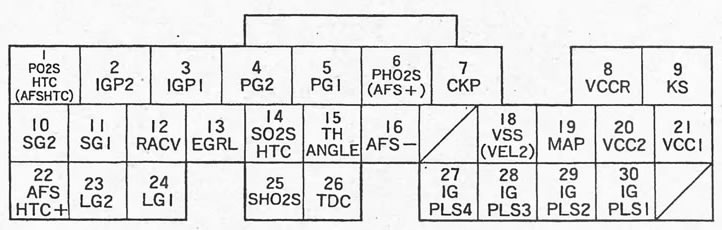
| Conclusion | Color | Sensor or element | Verification conditions | Voltage, V |
| 1A*7 | B/W | Heated oxygen sensor before catalytic converter | Ignition switch in the "ON" position | Vv |
| The engine is warm, idling | It's changing | |||
| 1A*1 | G | Heated fuel mixture sensor | Ignition switch in the "ON" position | Vv |
| The engine is warm, idling | 0 | |||
| 2A | Y/B | Supply voltage Relay No.2 | Ignition switch in the "ON" position | Vv |
| Ignition switch in the "OFF" position | 0 | |||
| 3A | Y/B | Supply voltage Relay No.1 | Ignition switch in the "ON" position | Vv |
| Ignition switch in the "OFF" position | 0 | |||
| 4A | IN | Mass No.2 | Constantly | 0 |
| 5A | IN | Mass No.1 | Constantly | 0 |
| 6A*7 | W | Heated oxygen sensor before catalytic converter | Engine warm, idling → throttle fully open | >0,6 |
| The throttle valve is closed quickly | <0,4 | |||
| 6A*2 | R | Heated fuel-air ratio sensor (+) | - | - |
| 7A | Bl | Crankshaft position sensor | Idling | Pulses |
| 8A*2 | Y | Vehicle speed sensor supply voltage | Ignition switch in the "ON" position | ≈5 |
| Ignition switch in the "OFF" position | 0 | |||
| 9A*2 | R/BI | Knock sensor | Ignition switch in the "ON" position | ≈5 |
| During detonation | Pulses | |||
| 10A | G/Y | Mass of sensors | Constantly | 0 |
| 11A | G/W | Mass of sensors | Constantly | 0 |
| 12A | B/R | Valve of the idle speed control system | Ignition switch in the "ON" position | ≈5 |
| Idling | It's changing | |||
| 13A*2 | W/B | EGR valve position sensor | Idling | ≈1,2 |
| The valve is fully open | ≈3,8 | |||
| 14A*5 | B/W | Heated oxygen sensor after catalytic converter | Ignition switch in the "ON" position | Vv |
| The engine is warm, idling | It's changing | |||
| 15A | R/B | Throttle Position Sensor | The throttle valve is fully open | 4,14-4,82 |
| The throttle valve is completely closed | 0,44-0,56 | |||
| 16A*1 | R | Heated fuel-air ratio sensor (-) | - | - |
| 18A*10 | W/G | Vehicle speed sensor | When moving | Pulses |
| 19A | G/R | Intake manifold vacuum sensor | Ignition switch in the "ON" position | ≈3 |
| Idling | ≈1,5 | |||
| 20A | Y/BI | Sensor supply voltage | Ignition switch in the "ON" position | ≈5 |
| Ignition switch in the "OFF" position | 0 | |||
| 21A | Y/R | Sensor supply voltage | Ignition switch in the "ON" position | ≈5 |
| Ignition switch in the "OFF" position | 0 | |||
| 22A*1 | W | Heated fuel-air ratio sensor (+) | Ignition switch in the "ON" position | Vv |
| 23A | R/Y | Mass of sensors | Constantly | 0 |
| 24A | R/Y | Mass of sensors | Constantly | 0 |
| 25A | W/R | Heated oxygen sensor before catalytic converter | Engine warm, idling → throttle fully open | >0,6 |
| The throttle valve is closed quickly | <0,4 | |||
| 26A | G | Camshaft Position Sensor | Idling | Pulses |
| 27A | Br | Ignition coil #4 | Ignition switch in the "ON" position | 0 |
| Idling | 0 < - > Vv Pulses | |||
| 28A | W/Bl | Ignition coil #3 | Ignition switch in the "ON" position | 0 |
| Idling | 0 < - > Vv Pulses | |||
| 29A | Bl/R | Ignition coil #2 | Ignition switch in the "ON" position | 0 |
| Idling | 0 < - > Vv Pulses | |||
| 30A | Y/G | Ignition coil #1 | Ignition switch in the "ON" position | 0 |
| Idling | 0 < - > Vv Pulses |
Connector "B"
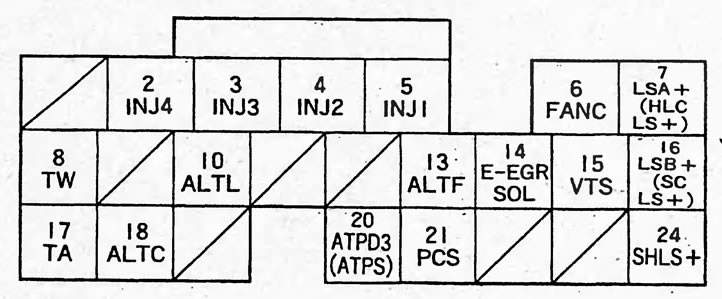
| Conclusion | Color | Sensor or element | Verification conditions | Voltage, V |
| 2B | Y | Nozzle #4 | Ignition switch in the "ON" position | Vv |
| Idling | It's changing | |||
| ZV | Bl | Nozzle #3 | Ignition switch in the "ON" position | Vv |
| Idling | It's changing | |||
| 4B | R | Nozzle #2 | Ignition switch in the "ON" position | Vv |
| Idling | It's changing | |||
| 5B | Br | Nozzle #1 | Ignition switch in the "ON" position | Vv |
| Idling | It's changing | |||
| 6B | G | Cooling system fan and air conditioner condenser fan relay | The fans are working | 0 |
| The fans are not working | Vv | |||
| 7B*8 | R/B | Pressure control solenoid valve "A" (+) | Ignition switch in the "ON" position | It's changing |
| 7B*9 | G/W | Solenoid valve for pressure distribution between pulleys (+) | Ignition switch in the "ON" position | It's changing |
| 8B | R/W | Coolant temperature sensor | Ignition switch in the "ON" position | 0 |
| When the engine is running | 0,1-4,8 | |||
| 10V | W/BI | Generator, terminal "L" | Ignition switch in the "ON" position | 0 |
| Idling | Vv | |||
| 13B | W/R | Generator, pin "FR" | The engine is warm, idling | 0-5 |
| 14B*2 | Bl/R | EGR valve | When the valve is operating | It's changing |
| The valve is not working | 0 | |||
| 15B*1 | G/Y | Variable valve timing system valve | At low crankshaft speed | 0 |
| 16B*8 | B/R | Solenoid valve "B" pressure control (+) | Ignition switch in the "ON" position | It's changing |
| 16B*9 | Y/G | Solenoid valve for control of starting clutch (+) | Ignition switch in the "ON" position | It's changing |
| 17B | Kr/F | Intake Air Temperature Sensor | Ignition switch in the "ON" position | 0,1-4,8 |
| 18B | W/G | Generator | The engine is warm, idling | Vv |
| Light load | 0 | |||
| 20B*15 | R | Start inhibit switch (position "D3") | Automatic transmission selector in position "D3" | 0 |
| Other | 5<->Vb | |||
| 20B*16 | R | Start inhibit switch (position "S") | Automatic transmission selector in position "S" | 0 |
| Other | 5<->Vb | |||
| 21B | Y/BI | Fuel vapor accumulator solenoid valve | Idle speed, coolant temperature < 70°C | 0 |
| Idle speed, coolant temperature > 70°C | It's changing |
Connector "C"
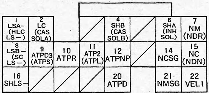
| Conclusion | Color | Sensor or element | Verification conditions | Voltage, V |
| 1C*8 | W/B | Pressure control solenoid valve "A" (-) | Ignition switch in the "ON" position | It's changing |
| 1C*9 | B/R | Pressure control solenoid valve (-) | Ignition switch in the "ON" position | It's changing |
| 2C*8 | Y/BI | Torque Converter Lockup Solenoid Valve | Works | Vv |
| It doesn't work | 0 | |||
| 2C*9 | G/Y | Solenoid valve "A" | Works | Vv |
| It doesn't work | 0 | |||
| 4C*8 | G/W | Gear shift solenoid valve "A" | Automatic transmission selector in position "D", "D3" (1st or 2nd gear) or position "2" | Vv |
| Automatic transmission selector in position "D", "D3" (3rd gear), position "D" (4th gear) or position "1" | 0 | |||
| 4C*9 | R/Y | Solenoid valve "B" | Works | Vv |
| It doesn't work | 0 | |||
| 6C*8 | Bl/B | Gear shift solenoid valve "A" | AKAP selector in position "D", "D3" (2 or 3 gear) or position "1", "2" | Vv |
| Automatic transmission selector in position "D", "D3" (1st or 2nd gear), Automatic transmission selector in position "D", "D3" (1 gear), Automatic transmission selector in position "D4" (4th gear) | 0 | |||
| 6C*9 | G/R | Start inhibit solenoid valve | Works | Vv |
| It doesn't work | Pulses | |||
| 7C*8 | W/R | Automatic transmission input shaft speed sensor | Automatic transmission selector in position "P", "N", engine running or in motion | Pulses |
| 7C*9 | R/BI | CVT drive pulley speed sensor | In addition to the automatic transmission selector position in "P", "N" | Pulses |
| 8C*8 | Br/W | Solenoid valve "B" pressure control (-) | Ignition switch in the "ON" position | It's changing |
| 8C*9 | Bl/R | Solenoid valve for control of starting clutch (-) | Ignition switch in the "ON" position | It's changing |
| 9C*11 | R | Overdrive Switch "D3" | Automatic transmission selector in position "D3" | 0 |
| Other | 5<->Vb | |||
| 9C*13 | R | Start inhibit switch (position "S") | Automatic transmission selector in position "S" | 0 |
| Other | 5<->Vb | |||
| 10C*13 | W | Start inhibit switch (position "R") | Automatic transmission selector in position "R" | 0 |
| Other | 5<->Vb | |||
| 11C*8 | BI | Start inhibit switch (position "2") | Automatic transmission selector in position "2" | 0 |
| Other | 5<->Vb | |||
| 11C*9 | BI | Start inhibit switch (position "L") | Automatic transmission selector in position "L" | 0 |
| Other | 5<->Vb | |||
| 12C*13 | BI/W | Start inhibit switch (position "P" or "N") | Automatic transmission selector in position "N" or "P" | 0 |
| Other | 5<->Vb | |||
| 13C*14 | R/B | Start inhibit switch (position "N") | Automatic transmission selector in position "N" | 0 |
| Other | 5<->Vb | |||
| 14C*8 | G | Automatic transmission output shaft speed sensor | Weight | 0 |
| 15C*8 | Bl | Automatic transmission output shaft speed sensor | Ignition switch in the "ON" position, front wheels are rotating | Pulses |
| 15C*9 | W/G | CVT driven pulley speed sensor | Automatic transmission selector in a position other than "N" or "P" | Pulses |
| 16C*9 | G/Y | Solenoid valve for pressure distribution between pulleys | Ignition switch in the "ON" position | Pulses |
| 20C*13 | Y | Start inhibit switch (position "D") | Automatic transmission selector in position "D" | 0 |
| Other | 5<->Vb | |||
| 21C*8 | W/G | Automatic transmission input shaft speed sensor (ground) | Weight | 0 |
| 22C*9 | W/R | Speed sensor #2 (ground) | Weight | 0 |
Connector "E"
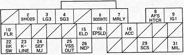
| Conclusion | Color | Sensor or element | Verification conditions | Voltage, V | |
| 2E*6 | B/Kr | Oxygen sensor after catalytic converter | The engine is warm, idling | The throttle valve is fully open | >0,6 |
| The throttle valve is completely closed | <0,4 | ||||
| ZE | Kch/F | Weight of control unit | Weight | 0 | |
| 4E*6 | Rz | Mass of sensors | Weight | 0 | |
| 6E*6 | B/W | Heated oxygen sensor after catalytic converter | Ignition switch in the "ON" position | Vv | |
| The engine is not warmed up, idling | It's changing | ||||
| 7E | Kr/F | Main relay | Ignition switch in the "ON" position | 0 | |
| Ignition switch in the "OFF" position | Vv | ||||
| 8E*1 | ABOUT | Heated mixture composition sensor | Ignition switch in the "ON" position | 0 | |
| 9E | W/C | Ignition switch | Ignition switch in the "ON" position | Vv | |
| Ignition switch in the "OFF" position | 0 | ||||
| 10E | 3/F | Fuel pump relay, relay #2 | Within 2 seconds when the ignition switch is set to the "ON" position | 0 | |
| Other | Vv | ||||
| 15E | G/R | Power supply voltage control system unit | Idle, low load | 2,5-3,5 | |
| Headlights are on | 1,5-2,5 | ||||
| 16E | Lg/B | Power Steering Fluid Pressure Sensor | The steering wheel is motionless | 0 | |
| When turning the steering wheel | Vv | ||||
| 18E | R | Air Conditioning Compressor Clutch Relay | Air conditioning switch in the "ON" position | 0 | |
| Air conditioner switch in the "OFF" position | Vv | ||||
| 22E | W/B | Brake light switch | Pedal not pressed | 0 | |
| The pedal is pressed | Vv | ||||
| 23E | Sb | Diagnostic connector | Ignition switch in the "ON" position | Vv | |
| 24E | Y | Electrical equipment control system MULTIPLEX | Ignition switch in the "ON" position | 5 | |
| After starting the engine with consumers on | Pulses | ||||
| 25E*9 | Bl/W | Vehicle speed sensor | When moving | Pulses | |
| 26E | WITH | Crankshaft position sensor | Idling | Pulses | |
| 29E | Br | Diagnostic connector | Closed | 0 | |
| Not closed | 5<->Vb | ||||
| 31E | G/O | Indicator "CHECK ENGINE" | The indicator is on | 0 | |
| The indicator does not light | Vv | ||||
Note:
- *1 - Models with D15B SOHC VTEC (lean burn) engine.
- *2 - Models with D15B SOHC VTEC, D17A SOHC engine.
- *3 - 2WD models with D15B SOHC engine.
- *4 - 4WD models with D15B SOHC, D15B SOHC VTEC (lean burn), D17A SOHC engine.
- *5 - 2WD models with D15B SOHC, D15B SOHC VTEC (lean burn) engine.
- *6 - Models with D15B SOHC VTEC engine (lean burn, except 2WD), D17A SOHC VTEC.
- *7 - Except for models with D15B SOHC VTEC (lean burn) engine.
- *8 - Models with automatic transmission.
- *9 - Models with CVT.
- *10 - Models with manual transmission, automatic transmission.
- *11 - Sedan, models with automatic transmission
- *12 - Sedan, models with CVT.
- *13 - Models with automatic transmission, with CVT.
- *14 - Hatchback, models with automatic transmission or with a CVT.
- *15 - Hatchback, models with automatic transmission.
- *16 - Hatchback, models with CVT.
(Article source on the website HondaBook)