
Contents: Sedan ⇊ Hatchback ⇊
Sedan
1. Disconnect the cable from the negative terminal of the battery.
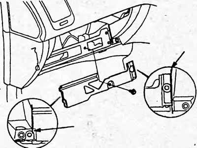
2. Remove the glove box, the lower panel of the glove box, and the front side trim.
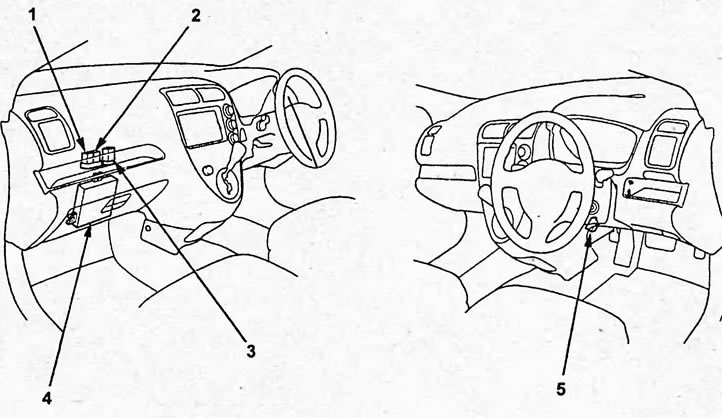
Layout diagram of the electronic control system elements for engines D15, D17 (hatchback). 1 - main relay No.2, 2 - main relay No.1, 3 - mixture sensor heater relay, 4 - control unit, 5 - diagnostic connector.
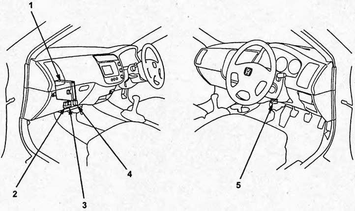
Layout diagram of the electronic control system elements of engines D15, D17 (sedan). 1 - control unit, 2 - main relay No.2, 3 - main relay No.1, 4 - mixture sensor heater relay, 5 - diagnostic connector.
3. Remove the relay, unscrew the bolts and remove the frame.
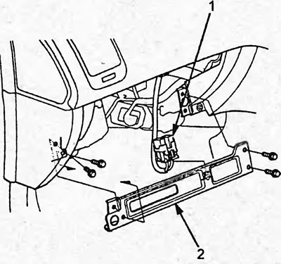
1 - relay, 2 - frame.
4. Disconnect the connectors (A) from the control unit.
5. Unscrew the bolt and nuts (C).
Tightening torque - 12 Nm
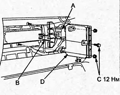
6. Remove the control unit.
7. Installation of parts is carried out in the reverse order of removal.
Hatchback
1. Disconnect the cable from the negative terminal of the battery.
2. Remove the glove box.
3. Unscrew the bolts securing the control unit to the bracket.
Tightening torque - 12 Nm
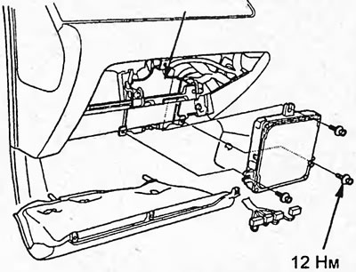
4. Remove the control unit.
5. Installation of parts is carried out in the reverse order of removal.