
Checking the axial clearance in the hub bearing
1. Jack up the front of the car and place it on stands.
Table. Wheel alignment angles.
| Installation angles | Size | |
| Front wheels | ||
| Convergence | 0±3 mm | |
| Wheel turning angles | Inner wheel | 40°00'±2°*1 38°00'+2° *2 |
| Outer wheel | 31°00' *1 30°00' *2 | |
| Longitudinal tilt of the pivot axis* | 1°40'±1° (2WD) 1°35'±1° (4WD) | |
| Collapse* | 0°00'±45' (2WD) 0°30'±45' (4WD) | |
| Rear wheels | ||
| Convergence | 2±2 mm | |
| Collapse* | -0°40'+45' (2WD) -0°35'±45' (4WD) | |
Note:
- the difference between the right and left sides should not exceed 1°.
- *1 - 2WD models with D15B engine;
- *2 - 2WD models with D17A engine, 4WD models and 5-door models produced since 10.2001.
2. To hold the brake disc (drum), tighten the nuts to the specified torque.
Tightening torque - 108 Nm
3. Install the dial indicator on the wheel hub as shown in the figure.
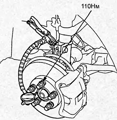
4. By pushing and pulling the wheel hub with your hands in the axial direction, measure the axial clearance in the wheel bearing.
Bearing clearance - 0-0.05 mm
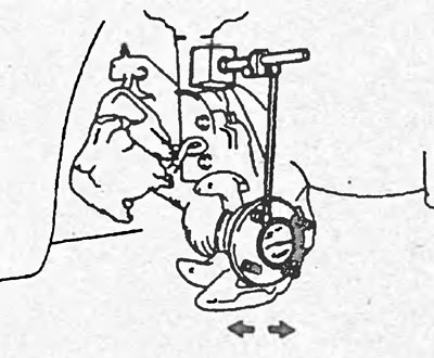
If the axial clearance of the wheel exceeds the established norm, first tighten the hub nut to the specified tightening torque and only then, if necessary, replace the bearing.
Removal
1. Jack up the front of the car and place it on stands.
2. Loosen the wheel mounting nuts and remove the wheel.
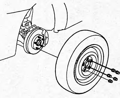
3. Loosen the brake pipe bracket mounting bolt (B).
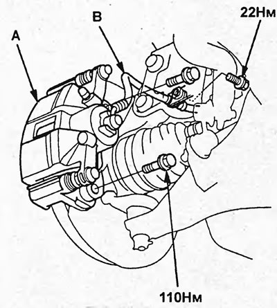
4. Loosen the bolts and remove the brake caliper assembly (A).
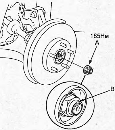
5. Unlock the nut rim (B) and unscrew the nut (A).
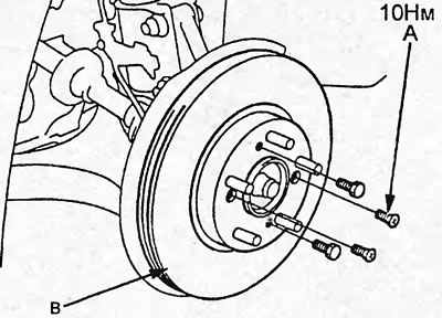
6. Loosen the screws (A), then remove the brake disc (B).
Note: To remove the disc, tighten the bolts as shown in the figure. Tighten the bolts alternately by 2 turns.
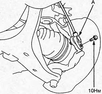
7. Loosen the bolt and remove the wheel speed sensor (A).
Note: Do not disconnect the wheel speed sensor connector.
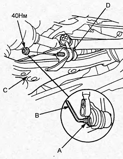
8. Hold the ball joint pin (A) with the Allen key (B), and loosen the stabilizer link mounting nut. Disconnect the stabilizer link (D) from the front suspension lower arm (C).
9. Remove the cotter pin and unscrew the nut. Using a special tool, disconnect the ball joint of the lower arm of the front suspension from the steering knuckle.
Note: When assembling, install the cotter pin as shown in the figure.
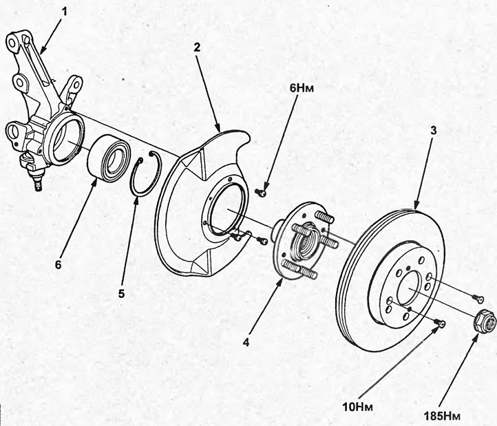
Removal and installation the steering knuckle and hub. 1 - steering knuckle, 2 - mudguard, 3 - brake disc, 4 - hub, 5 - retaining ring, 6 - bearing.
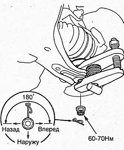
10. Loosen the bolts and nuts securing the front suspension strut.
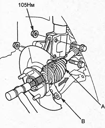
11. Using a plastic hammer, loosen the drive shaft fit. Disconnect the drive shaft (A) and the steering knuckle with the hub (B).
12. Using a press and a special tool, press the hub out of the steering knuckle.
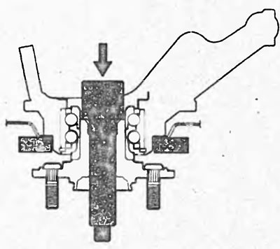
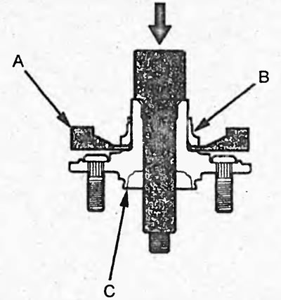
13. If the inner bearing ring remains on the hub, use the special tool (A) and a press to remove the inner ring (B) from the hub (C).
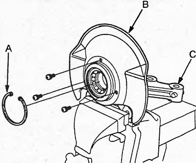
14. Remove the retaining ring (A), unscrew the screws and remove the mudguard (B) from the steering knuckle (C).
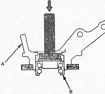
15. Using a press and a mandrel, press the bearing (B) out of the steering knuckle (A).
Installation
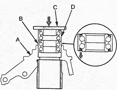
1. Install a new bearing (B) into the steering knuckle (A), then install the old bearing (D) and steel plate (C) as shown in the figure, and press the bearing in.
2. Install the snap ring (A) into the steering knuckle (D).
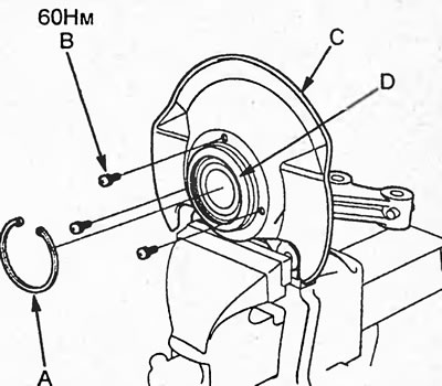
3. Install the mudguard (C) onto the steering knuckle and tighten the screws (B).
Tightening torque - 9 Nm
4. Using special tools and a press, press the hub (B) into the steering knuckle (A).
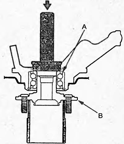
5. Install the hub assembly with the steering knuckle in the reverse order of removal. Note: After installation, check and, if necessary, adjust the wheel alignment angles.
(Article source on the website: HONDABOOK)