
HondaBook.ru
Auto companies Volkswagen Auto companies Ford Auto companies Lada Auto companies Skoda Auto companies BMW Auto companies Mazda Auto companies Peugeot
English Русский
Български
Беларускі
Український
Српски
Hrvatski
Română
Polski
Slovenský
Magyar
Bookmark Contacts Sitemap   


Accord Civic Fit / Jazz CR-V HR-V Others Articles
Accord 3 (1985-1989) Accord 6 (1997-2002)

Wheel Hub, Steering Knuckle & Bearings — 1984-85 Accord (Honda Accord 3)

  • Main
  • Honda Accord
  • 3 (1985-1989)
  • Chassis and running gear
  • Front suspension
  • Wheel Hub, Steering Knuckle & Bearings — 1984-85 Accord
0
WARNING: This procedure REQUIRES the use of special tools or equivalent. A hydraulic press, punches of the correct diameters, and a support are required to disassemble the hub and bearing. (Special tool numbers shown are specific to Honda)
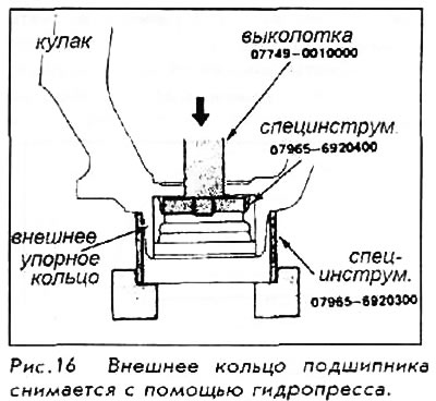

WARNING: This procedure REQUIRES the use of…


1. Pull the lock key out of the spindle, then loosen the nut. Loosen the wheel nuts slightly.

2. Raise and securely support the vehicle. Remove the front wheel and spindle nut.

3. After unscrewing the brake caliper mounting bolts, remove the caliper from the knuckle. Do not leave the caliper hanging on the brake hose, but secure it with a wire.
3. After unscrewing the brake caliper mounting…


4. Remove the brake disc mounting bolts (if any). Screw two 8x1.25x12mm bolts into the brake disc removal holes and tighten them to push the disc off the hub.


Tighten each bolt only 2 turns at a time to avoid warping and binding of the disc.


5. Remove the tie rod from the knuckle using the tie rod end removal tool. Be careful not to damage the ball joint seals.

6. Remove the cotter pin from the lower arm ball joint and remove the castle nut.

7. Remove the lower arm from the knuckle using a ball joint puller.

8. Loosen the locking bolt holding the strut to the knuckle. Tap the top of the knuckle with a hammer to disengage it from the shock absorber.

9. Remove the knuckle and hub, if still attached, by sliding the assembly off the drive shaft.

10. Remove the hub from the knuckle using a suitable punch and hydraulic press.

Removal the bearing


11. Remove the mud shield and snap ring, then remove the outer bearing.
11. Remove the mud shield and snap ring, then…


12. Turn the joint over and remove the inner, dust seal, bearing and inner ring.

13. Press the outer bearing ring out of the knuckle using the appropriate special tool and a hydraulic press.

14. Using a bearing puller, remove the inner race of the outer bearing from the hub.

15. Remove the outer dust seal from the hub.
15. Remove the outer dust seal from the hub.


Whenever wheel bearings are removed, they must be replaced with new sets of bearings and outer dust seals.


16. Clean all old grease from drive shafts and spindles.

17. Remove all old grease from the hub and knuckle, dry completely and wipe all components clean.

18. When assembling new bearings, you must use special grease for wheel bearings.

19. Apply a moderate amount of lubricant to the inside surfaces of the rotor and hub (do not overfill the hub with grease).

20. Before installation, apply a small amount of lubricant to the spindle and the lip of the inner seal.

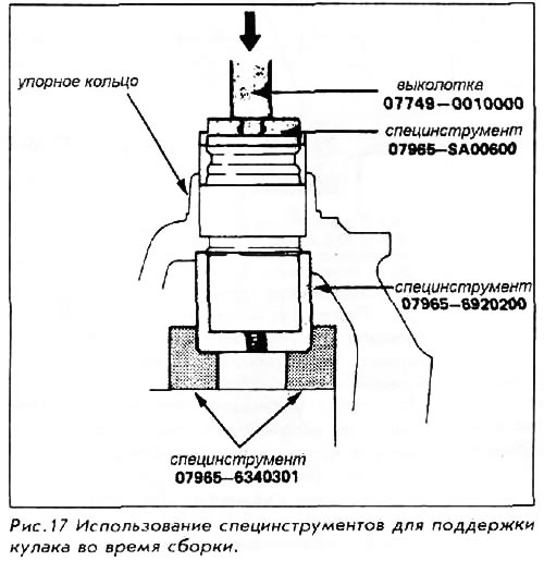
21. To install the bearings, press the outer bearing race into the knuckle using the special tools (used above, plus the base of the puller). Do not exceed 2.5 tons of pressure.

22. Install the outer ball bearing and its inner race into the knuckle.

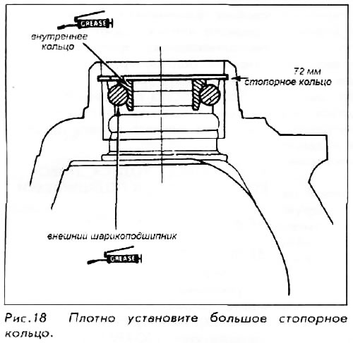
23. Install the retaining ring. Lubricate the grooves around the outer dust seal lip.

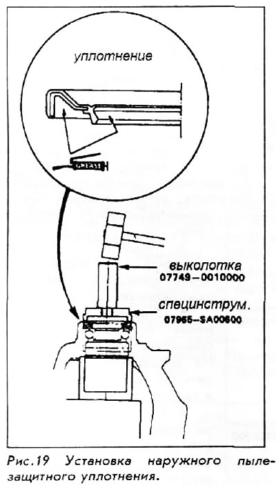
24. Press the seal into the knuckle using a seal punch and hammer until it is flush with the knuckle surface.

25. Install the mudguard, then turn the knuckle upside down and install the inner ball bearing and its inner race.
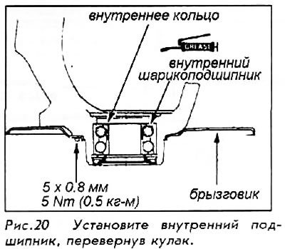
25. Install the mudguard, then turn the knuckle…


26. Place the hub in the press holder; place your fist in the press and press down. Do not exceed 2 tons of pressure during installation.
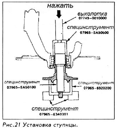


26. Place the hub in the press holder; place your…


27. Fill the grooves around the inner dust cover with grease.

28. Use a seal punch to seat the seal into the knuckle.

29. Install the knuckle. Always use a new spindle nut on the end of the drive shaft. Tighten the spindle nut securely. After lowering the vehicle onto the wheels, tighten the spindle nut to 190 Nm.

[Material obtained from the website «www.HondaBook.ru»]
This article is available at: russian, bulgarian, belarusian, ukrainian, serbian, croatian, romanian, polish, slovak, hungarian
This information has been verified: Yaroslav Shiryaev
Share with friends:
◀ Previous
Accord 3: Front suspension
Next ▶

Lower suspension arms — removal and installation
Upper control arm — removal and installation
Reaction bar — removal and installation
Anti-roll bar — removal and installation
Lower ball joint inspection
Wheel Hub, Steering Knuckle & Bearings — 1986-89 Accord, 1983-91 Prelude
Wheel Hub, Steering Knuckle & Bearings — 1990-91 Accord
Front wheel alignment
Front Suspension Tightening Torque Specifications
See also other articles from Honda manuals:
Front wheel steering knuckle and hub Honda Civic 7 (2000-2005)
Front wheel steering knuckle and hub Honda Fit 1 (2001-2008)
Replacing steering knuckle/hub/wheel bearing Honda CR-V 2 (2002-2006, petrol)
Steering wheel — disassembly and assembly Honda HR-V 1 (1998-2006, petrol)
Front Suspension Steering Knuckle and Hub — Wheel Bearing Replacement Honda Avancier 1 (1999-2003, petrol)
Link in different formats to this article
Comments and feedback from visitors
No comments yet


How much will 50 + 31 ?


Accord 6 (1997-2002) 
  • General information
  • Introduction to the guide
  • User manual
  • Maintenance
  • Power unit
  • Four-cylinder engines
  • Six-cylinder engines
  • Engine overhaul
  • Cooling system
  • Heater and air conditioner
  • Power and exhaust systems
  • Engine electrical equipment
  • Engine management
  • Transmission
  • Mechanical gearbox
  • Automatic gearbox
  • Clutch and drive shafts
  • Chassis and running gear
  • Brake system
  • Car suspension
  • Steering
  • Body and interior
  • Exterior (external elements)
  • Interior (internal elements)
  • Electrical equipment
  • Equipment and devices
  • Electrical circuits
Accord 3 (1985-1989) 
  • General information
  • Maintenance
  • Power unit
  • Engine adjustment
  • Engine repair
  • Engine electrics
  • Emission management
  • Engine management (carburetor)
  • Electronic injection
  • Programmable injection
  • Schematic of emission system
  • Fuel system
  • Feedback management
  • Transmission
  • Manual gearbox
  • Automatic gearbox
  • Clutch
  • Chassis and running gear
  • Front suspension
  • Rear suspension
  • Steering
  • Brake system
  • Electrical equipment
  • Ventilation and heating
  • Air conditioner
  • Cruise control system
  • Equipment and devices
HondaBook.ru © 2018–2026 • Mobile version • Sitemap: EN BG BY UA RS HR RO PL SK HU • Feedback • Driver Information • Search system • Bookmark
Accord 3 (1985-1989) • Accord 6 (1997-2002) • Civic 3 and 4 (1983-1991) • Civic 5 and 6 (1991-2000) • Civic 6 (1995-2000) • Civic 7 (2000-2005) • Civic 8 (2005-2011) • Fit 1 (2001-2008) • CR-V 1 (1995-2001) • CR-V 2 (2002-2006) • HR-V 1 (1998-2006) • Avancier 1 (1999-2003) •
 
This website uses cookies to ensure proper functioning. By clicking "OK," you agree.