
Checking axial play and lateral runout
1. Checking the axial play is as follows:
- a) Install the camshaft in the engine and secure it with bearing caps;
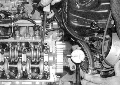
- b) Fix the dial gauge on the cylinder head, resting it with a plunger on the end of the shaft (see accompanying illustration); c) Using a large screwdriver as a lever, pull the shaft all the way back and zero the meter, then push the shaft forward and read the instrument reading;
- d) Compare the measurement result with the requirements Specifications;
- e) Excessive axial play indicates wear on the camshaft or head.
2. To check lateral runout:
- a) Lay the camshaft removed from the engine in two V-shaped prisms, then press the plunger of the dial gauge against the neck of the central bearing and measure the amount of runout when the shaft rotates;
- b) Compare measurement results with requirements Specifications;
- c) In case of excessive combat, the camshaft must be replaced.
Withdrawal
1. Remove the cylinder head cover (see Removal and installation of a cover of a head of cylinders).
2. Bring the piston of the first cylinder to the TDC position (see Bringing the piston of the first cylinder to the top dead center position (TDC)).
3. Remove the ignition distributor (see chapter Engine electrical equipment).
4. If necessary, unscrew the camshaft gear mounting bolt to remove it from the trunnion.
Note. To block the shaft from turning, insert a screwdriver through one of the holes in the gear.
5. Remove rocker assembly (see Removal, condition check and installation of rocker arm assembly). If the camshaft bearing caps are to be removed from the assembly, they must be marked in the order of installation (mark asymmetrically to ensure proper lid orientation).
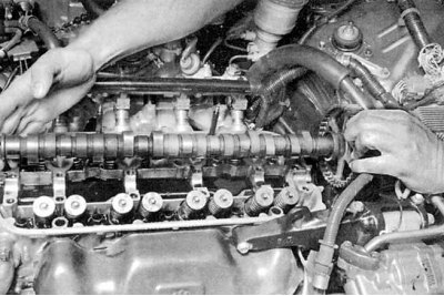
6. Remove the crankshaft (see accompanying illustration).
Examination
1. Check the bearing washers of the shaft and the inner surfaces of the bearing caps for scratches and burrs. In case of detection of serious defects, the cylinder head must be replaced with a new or remanufactured one. With calibrated plastic wire (Plastigauge set) measure the operating clearances in the bearings. Compare measurement results with requirements Specifications.
Note. Instructions for using the Plastigauge kit are given in Installing the crankshaft and checking the operating clearances of the main bearings and Installing connecting rod and piston assemblies and checking the working clearances in the connecting rod bearings of the crankshaft Parts General and overhaul of the engine of this Chapter. If the clearance of any of the bearings is out of range, replace the camshaft.
2. Assess the degree of wear of the camshaft cams:
- a) Carefully inspect the forming surfaces of the working ledges of all cams, checking them for scratches, scuffs and signs of uneven wear;
- b) If a defect is found in at least one of the cams, replace the camshaft. Do not forget about the need to identify the causes of wear - check the engine oil for the presence of abrasive particles in it. Check the patency of the oil pump and all oil flows (wear of the cam lifts is most often associated with oil contamination or a violation of its supply);
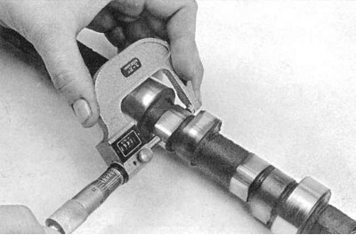
- c) Using a micrometer, measure the height of the cams (see accompanying illustration). Compare the measurement results, if necessary, replace the camshaft. 3. Check the working surfaces of the rocker arms of the valve drive for signs of wear, scuffs, cavities and other defects.
4. If any of the defects listed above are detected, the condition of the engine oil and the serviceability of its supply to the cylinder head should be checked. Only after identifying and eliminating the cause of the violation, proceed with the installation of replacement components (head, camshaft or rocker arm assembly).
Installation
1. Thoroughly clean the camshaft, the beds of its bearings in the cylinder head and covers, as well as the rocker arms of the valve drive. Try to completely remove the slightest traces of sludge and dirt. Use only a clean, lint-free cloth to wipe components.
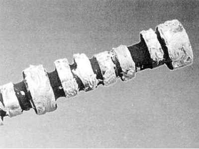
2. Lubricate the cams and bearing journals of the camshaft with special assembly grease (see accompanying illustration).
Attention! If the shaft is not thoroughly lubricated before installation, serious damage to the bearings and cams can result in the first seconds after the engine is started, before normal oil circulation begins.
3. Gently lower the camshaft into the cylinder head. Using as a mandrel a socket head of the appropriate size or a piece of pipe of a suitable diameter, put the oil seal in its regular place (open side with the spring installed in the groove inside).
4. Replace the rocker assembly (see Removal, condition check and installation of rocker arm assembly).
5. Having turned the shaft in an appropriate way, put the gear wheel on its front trunnion (marking "UP" at 12 o'clock).
6. Install the timing belt and related components (see Removing, checking the condition and installing the gas distribution belt and timing gears).
Attention! If during the maintenance of the head the position of the crankshaft was knocked down, take care when installing the belt to align the alignment marks of its gear (see Removing, checking the condition and installing the gas distribution belt and timing gears).
7. Turn out spark plugs and turn a cranked shaft manually, checking correctness of installation of phases of gas distribution. After two turns, the timing marks of the gears should return to their original position. Otherwise, remove the belt and achieve the desired alignment of the marks.
Attention! If in the process of cranking the crankshaft there is resistance, the procedure should be stopped immediately!
8. Further installation is carried out in the reverse order to the dismantling of the components.