
General information
Some Honda models are equipped with Variable Valve Timing Electronic Control (VTEC). Civic models can use one of two different types of VTEC (VTEC and VTEC-E).
The difference between conventional engines and engines equipped with the VTEC system is in the configuration and operating principle of the valve mechanism. The design of the engine block and all mounted units and assemblies, as well as the lubrication and cooling system organization schemes on both units are the same. Externally, the engine equipped with the VTEC system is distinguished by the presence of a convex inscription with the corresponding content (VTEC) on top of the cylinder head cover.
The on-board processor of models equipped with the VTEC system is capable of adjusting the phases of operation and the amount of opening of the intake valves by using different sizes of camshaft cams. The processor, depending on the data received from the information sensor, either turns the system on or off.
The following are used as initial parameters for both types of VTEC systems:
- a) Engine speed (rpm);
- b) Vehicle speed (mph);
- c) Throttle Position Sensor (TPS) Output Signal;
- d) Current engine load determined by the absolute pressure sensor (MAP) readings;
- e) Coolant temperature.
The layout and operating principle of VTEC-E systems are somewhat different from those of VTEC systems (see below).
VTEC-E (D16Y5)
The camshaft is equipped with both primary and secondary cams for the intake valve drive. The cams differ in both shape and lift height, i.e. parameters that determine the duration and degree of valve opening.
At low engine speeds, the secondary valves are operated by the camshaft's own cams, which have a very low lift and a pointed shape (i.e. the valves open only slightly and for a very short time), keeping the atomized fuel from consolidating inside the cylinder head. At the same time, good torque is developed with high throttle response.
If there is a need to increase engine output, the secondary rocker arms are locked with the primary ones using a special hydraulic device with electronic control.
Note: The secondary rocker arms are no longer in contact with their own cams until the system is disengaged, at which point both valves open to their full height and duration, providing increased engine speed and power.
VTEC (D16Y8)
The cams of the primary and secondary intake valves of the camshaft in this system are identical in shape and lift height. Between them is an additional third cam, also called intermediate cams. These intermediate cams are distinguished by a greater height and lesser lift sharpness, which ensures a greater value and duration of valve opening.
At low engine speeds, both the primary and secondary intake valves are actuated by their own cams and open to the same height and for the same duration (unlike the VTEC-E system). When it is necessary to increase the engine output, the rocker arms of both intake valves are locked with the intermediate rocker arm by means of a special hydraulic device with electronic control. In this case, the duration and height of opening of both valves are determined by the shape of the intermediate cam, which is distinguished by a greater height and a less pointed lift.
Note: The primary and secondary rocker arms will no longer contact their own cams until the system is disengaged.
The system allows achieving optimal torque at both low and high engine speeds, depending on the current load applied to it.
Checking the status of components
Valve clearance correctors (vTEC only)
Four valve clearance adjusters are placed in holders, forming a kind of hydraulic tappets.
1. Unbolt and remove the holder assembly.
2. Remove the individual corrector assemblies from the holder.
3. Use your fingers to check the freedom of movement of each of the correctors. If any jamming points are detected, replace the defective assemblies.
Phase distribution plate, bushing and return spring (only VTEC-E)
Four phase distribution plates with return springs (see illustration below) seated in the camshaft holders on the intake rocker arm axis.
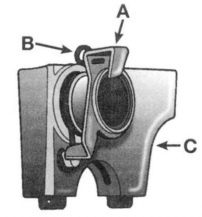
A) Phase distribution plate
IN) Return spring
WITH) Cam holder
Note: As shown in the illustration, the assembly sleeve is equipped with shoulders to hold the spring.
1. Check the reliability of the spring fastening on the camshaft holder and the phase distribution plate.
2. Inspect the components for scratches, chips, signs of overheating and other damage.
3. Defective parts are subject to replacement.
4. The assembly order is clear from the illustration above.
Synchronizing assemblies
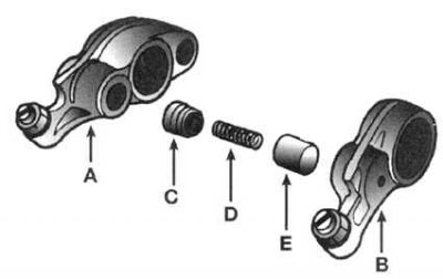
1. After removing and dismantling the rocker arm assemblies (see Removal, condition check and installation of rocker arm assembly), also extract the components of the synchronization nodes (see accompanying illustrations).
Only VTEC-E D16Y5:
- A) Primary valve rocker arm
- IN) Secondary valve rocker arm
- WITH) Blocker piston
- D) Lock spring
- E) Synchronizing piston
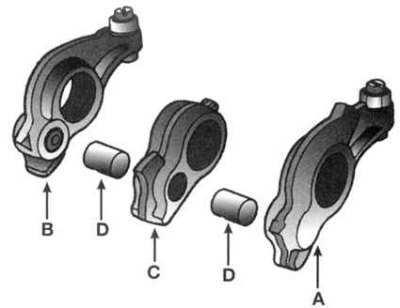
Only VTEC D16Y8:
- A) Primary valve rocker arm
- IN) Secondary valve rocker arm
- WITH) Intermediate rocker arm
- D) Synchronizing pistons
2. Check the condition of the locking spring (only VTEC-E).
3. Inspect other components of the assembly (rocker arms with synchronizing pistons). If signs of wear, abrasions, deep scratches, scoring or traces of overheating are detected, replace the defective components.
4. Assembly is carried out in the reverse order of dismantling.
Note: Assemble the components of each cylinder assembly together, secure them with a rubber bandage, and only then install them on the axle (see Removal, condition check and installation of rocker arm assembly).
VTEC Lockup Solenoid Valve
Malfunctions in the VTEC lock-up solenoid valve circuit result in the activation of the "Check Engine" warning lamp on the vehicle's instrument cluster. At the same time, a malfunction code (DTC) P1259 is stored in the control unit's memory. The VTEC lock-up valve with an integrated pressure sensor-switch is similar in design to that used in the VTEC system of Integra models. A description of the procedure for checking the proper functioning of the assembly is given in Part Engine Repair Without Removing It From the Vehicle - Integra Models of this Chapter.
Oil sprayer
Cm. Removal, condition check and installation of rocker arm assembly.
Primary valve rocker arm
Cm. Removal, condition check and installation of rocker arm assembly.
Secondary valve rocker arm
Cm. Removal, condition check and installation of rocker arm assembly.
Intermediate rocker arm (vTEC only)
Cm. Removal, condition check and installation of rocker arm assembly.
Intermediate camshaft (vTEC only)
Cm. Removal, condition check and installation of rocker arm assembly.