
Contents: Removal and inspection ⇊ Installation ⇊
Removal and inspection
1. Remove the cylinder head cover (see Section Removal and installation cylinder head covers).
2. Bring the piston of the first cylinder to the TDC position (see Section Bringing the piston of the first cylinder to the top dead center (TDC) position).
3. Remove the ignition distributor (see Chapter Engine electrical equipment).
4. Remove the timing belt and balance shaft drive belt (see Sections Removal, condition check and installation of rocker arm assembly and Removal, condition check and installation of camshafts).
5. If necessary, unscrew the camshaft gear mounting bolt in order to remove it from the journal.
Note: To prevent the shaft from turning, insert a screwdriver through one of the holes in the gear.
6. Remove the rocker arm assembly (see Section Removal and installation of exhaust manifolds). If the camshaft bearing caps are to be removed from the assembly, they must be marked in the order of installation (mark asymmetrically to ensure that the caps are correctly positioned during installation).
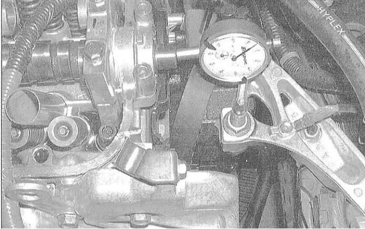
7. Checking the axial clearance is performed as follows:
- a) Install the camshaft into the engine and secure it with the bearing caps (the rocker arm assembly is removed);
- b) Secure the dial gauge to the cylinder head, resting its plunger against the end of the shaft;
- c) Using a large screwdriver as a lever, pull the shaft back as far as it will go and reset the meter to zero, then push the shaft forward and read the meter reading;
- d) Compare the measurement result with the requirements of the Specifications;
- e) Excessive axial clearance indicates wear of the camshaft or cylinder head.
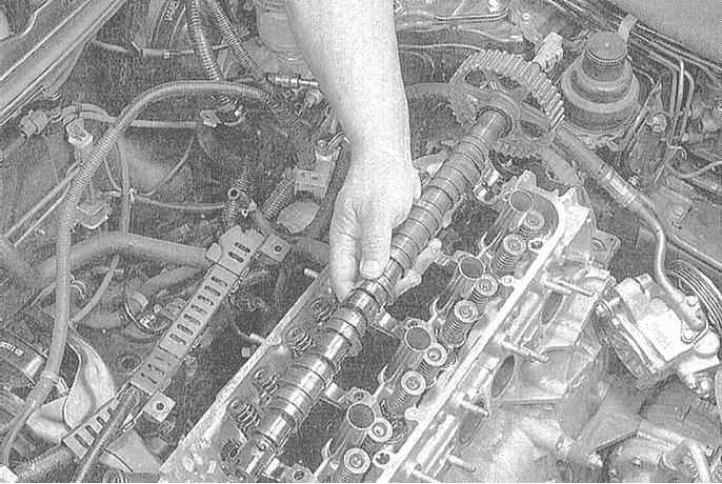
8. Remove the camshaft, wipe it dry with a clean rag or paper towel and transfer it to a workbench.
9. To check the lateral runout (it would be better to entrust this check to car service specialists):
- a) Place the camshaft removed from the engine in two V-shaped prisms, then press the plunger of the dial gauge against the journal of the central bearing and measure the runout value when the shaft rotates;
- b) Compare the measurement results with the requirements of the Specifications;
- c) If the runout is excessive, the camshaft must be replaced.
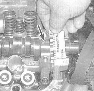
10. Check the camshaft bearing journals and the inner surfaces of the bearing caps for scratches and scoring. If serious defects are found, the cylinder head must be replaced with a new or reconditioned one. Using a calibrated plastic wire (Plastigage kit), measure the working clearances in each of the bearings. Compare the measurement results with the requirements of the Specifications. If the clearance of any of the bearings is outside the permissible range, replace the camshaft and/or cylinder head.
Note: Instructions for using the Plastigage kit are provided in Sections Installing the crankshaft and checking the main bearing clearances and Installation of connecting rod and piston assemblies and checking the size of working clearances in the connecting rod bearings of the crankshaft.
 |
 |
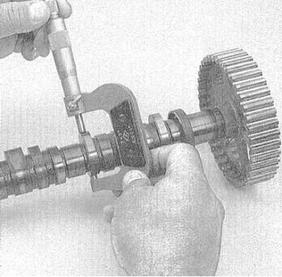
11. Assess the degree of wear of the camshaft cams:
- a) Carefully inspect the working surfaces of all cams, checking for scratches, burrs, cavities and signs of uneven wear;
- b) If a defect is detected in at least one of the cams, replace the camshaft. Do not forget about the need to identify the causes of wear - check the engine oil for the presence of abrasive particles. Check the condition of the oil pump and the patency of all oil flows (wear of the cam lifts is most often associated with contamination of the oil or a violation of its supply);
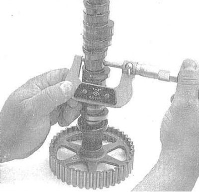
- c) Using a micrometer, measure the cam lobe height. Compare the measurement results with the specifications, replace the camshaft if necessary.
12. Check the working surfaces of the valve drive rocker arms for signs of wear, abrasions, cavities and other defects.
13. If any of the above defects are detected, the condition of the engine oil and the correctness of its supply to the cylinder head should be checked. Only after identifying and eliminating the cause of the violation, proceed to install the replacement components (head, camshaft or rocker assembly).
Installation
1. Thoroughly clean the camshaft, its bearing seats in the cylinder head and covers, and the rocker arms of the valve drive. Try to completely remove the slightest traces of sludge and dirt. Use only a clean, lint-free cloth to wipe the components.
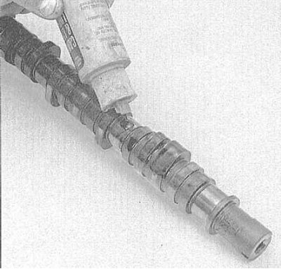
2. Lubricate the camshaft cams and bearing journals with special assembly grease.
Caution! Failure to lubricate the shaft thoroughly before installation can result in serious damage to the bearings and cams in the first seconds after starting the engine before normal oil circulation begins. Carefully lower the camshaft into the cylinder head (its gear should be turned with the "UP" mark facing up).
3. Install the rocker arm assembly (see Section Removal, condition check and installation of rocker arm assembly).
Note: On VTEC models, be sure to clean the oil spray nozzle.
4. Adjust the position of the camshaft gear so that its two side marks are aligned with the upper edge of the cylinder head. Install the timing belt and balance shaft drive belt with associated components (see Sections Removal, condition check and installation of gear wheels and balance shaft drive belt and Removal, condition check and installation of the timing belt and timing drive gears).
5. Further installation is carried out in the reverse order of dismantling the components.
[Full text available on the portal: HONDABOOK.ru]