
General information
VTEC was developed by Honda to provide dynamic control of valve timing and valve opening. Engines equipped with this system are marked with the VTEC inscription molded on the cylinder head cover. Corresponding engine serial number (F23A1 or F23A4) knocked out on the side of the block facing the radiator.
The difference between engines equipped with a VTEC system and the basic version lies solely in the principle of controlling the valve timing and features of the valve mechanism. The design of the reduced set of the engine block, the scheme for organizing lubrication and cooling systems remain the same, as well as the list, arrangement and location of attachments.
The on-board processor of the engine management system of VTEC-equipped models is able to adjust the timing and degree of opening of the intake valves through the use of camshaft cams of various sizes and shapes. Depending on the data coming from the information sensor, the processor either turns on or off the system.
The order of operation of both types of VTEC systems is determined by the following initial parameters:
- a) Engine speed (rpm);
- b) Vehicle speed (mph);
- c) Throttle position sensor output (TPS);
- d) The current load on the engine, determined by the readings of the absolute pressure sensor in the intake manifold (IDA);
- e) Coolant temperature.
The camshaft is equipped with three cams for driving each of the engine intake valves, which differ from each other in profile shape and lift height, which determine the duration and amount of opening of the respective valves.
At low engine speeds, the secondary intake valves are actuated by their own camshaft lobes, which have a very low lift and pointed shape (those. valves, in comparison with the primary ones, open only slightly and for a very short time), keeping the atomized fuel from consolidating inside the cylinder head. At the same time, good lower torque is developed with high response speed, which determines excellent traction characteristics and high acceleration of the car. In this case, the primary cams function in normal mode, creating swirls of the combustible mixture in the combustion chambers.
If there is a need to increase the output of the engine, the secondary rocker arms are blocked through the intermediate ones with the primary special synchronizing pistons. Synchronizing pistons are electronically controlled hydraulically. When the rocker arms are blocked, both intake valves begin to open in the same mode, and the degree and duration of their opening are determined by the shape of the intermediate rocker arm cam and have an increased value.
Note. The secondary rocker arms are no longer in contact with their own cams until the system is turned off. In this case, both valves open to full height and with maximum duration, providing an increase in engine speed and output.
Checking the Status of Components
Note. Checking some of the VTEC components requires removing the rocker assembly (see Section Removal, condition check and installation of rocker arm assembly).
VTEC Lockout Control Solenoid
Note. Failure of the VTEC solenoid valve operation leads to the recording of a fault code in the memory of the self-diagnosis unit and to the operation of the warning lamp "Check engine" (see chapter Engine management).
The most common cause of VTEC malfunction is a malfunction of the solenoid valve or its filter. Regularly changing the engine oil and filter will help avoid annoying failures.
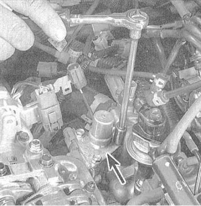
1. The VTEC lockup control solenoid is located on the right rear of the cylinder head (from the side of the rear bulkhead of the engine compartment).
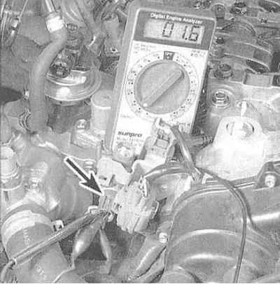
2. Check for continuity between the solenoid valve connector and body ground. There must be a resistance of 14÷30 Ohm; otherwise the VTEC solenoid valve must be replaced.
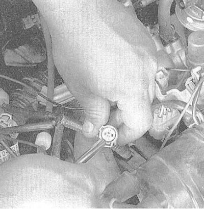
3. Ignition OFF, disconnect the harness connector from the VTEC pressure sensor switch and check for continuity between the two sensor switch terminals on the VTEC solenoid valve. Conductivity must be present, otherwise replace the sensor-switch. 4. Turn on the ignition and measure the voltage between the blue-black wire terminal of the pressure switch and ground. The required value is about 12 V, otherwise, check the wire in the area between the connector and the PCM for breaks or a short to ground.
5. With the ignition on, measure the voltage between the connector terminals of the pressure sensor wiring harness connector. There must be a voltage of 12 V, otherwise the break in the brown-black wire must be repaired.
6. Separate the solenoid valve and manually check the freedom of movement of its plunger. When reinstalling the valve, be sure to replace the seal.
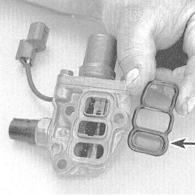
7. Completely remove the solenoid valve assembly from the cylinder head and check the condition of the gasket and filter patency. Clean the assembly and install it in place, after replacing the gasket.
Note. Strainer leakage is the most likely cause of VTEC system failures.
Rocker arms
1. Bring the piston of the first cylinder to the TDC position of the end of the compression stroke (see Section Bringing the piston of the first cylinder to the top dead center position (TDC)). Remove the cylinder head cover (see Section Removal and installation of a cover of a head of cylinders).
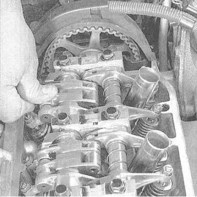
2. Press your finger on the intermediate rocker of the intake valve kit of the first cylinder - it should move independently of the primary and secondary rocker assembly. Proceeding in the same order, check up serviceability of functioning of rocker arms of inlet valves of the remained cylinders (the corresponding pistons are moved to TDC).
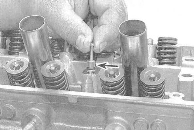
Valve clearance adjusters
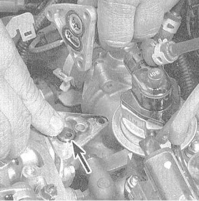
1. Assemblies of four correctors are planted in special pockets in the engine cylinder head.
2. Separately, remove each of the correctors from the cylinder head.
3. Check the proper functioning of the correctors by pressing the plungers with your finger. The plunger should move with slight resistance, gradually increasing as it goes deeper, otherwise replace the defective assembly.
Sync builds
1. After removing and dismantling the rocker assemblies (see Section Removal, condition check and installation of rocker arm assembly), also extract the components of the sync nodes (see below).
VTEC Timing Assembly Components:
- a) Primary valve rocker (primary rocker);
- b) Secondary valve rocker (secondary rocker);
- c) Intermediate rocker;
- d) Synchronizing piston A;
- e) Timing piston B;
- f) distribution piston.
2. Check up a condition of a distributive spring. Make sure it doesn't burst or sag. Replace if necessary.
3. Check all other components (rocker arms and synchronizing pistons) for signs of wear, abrasions, scuff marks, overheating and other defects. Replace defective parts. Remove the oil spray jet from the third camshaft holder, clean it and reinstall it (engines without VTEC). 4. Assembly is carried out in the reverse order to the dismantling of the components.
Note. Gather together the components of the assemblies of each of the cylinders, fasten them with a rubber band, only then install them on the axle (see Section Removal, condition check and installation of rocker arm assembly).