
HondaBook.ru
Auto companies Volkswagen Auto companies Ford Auto companies Lada Auto companies Skoda Auto companies BMW Auto companies Mazda Auto companies Peugeot
English Русский
Български
Беларускі
Український
Српски
Hrvatski
Română
Polski
Slovenský
Magyar
Bookmark Contacts Sitemap   


Accord Civic Fit / Jazz CR-V HR-V Others Articles
Civic 3 and 4 (1983-1991) Civic 5 and 6 (1991-2000) Civic 6 (1995-2000) Civic 7 (2000-2005) Civic 8 (2005-2011)

Brake system — general information (Honda Civic 6)

  • Main
  • Honda Civic
  • 6 (1995-2000)
  • Chassis and running gear
  • Brake system
  • Brake system — general information
0
Contents: Typical layout of front disc brake…⇊ Typical layout of rear disc brake…⇊ General information ⇊ Master brake cylinder (MBC) ⇊ Regulator valve ⇊ Vacuum brake booster ⇊ Parking brake ⇊ Precautionary measures ⇊
The vehicles described in this Manual are equipped with a hydraulic brake system with vacuum booster. Disc brakes are always installed on the front wheels (see illustration below), while the rear wheel mechanisms can have either a disc (see illustration below), as well as the drum design.

Typical layout of front disc brake components
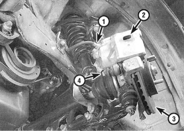


1 - Brake hose; 2 - Support; 3 - Brake disc; 4 -…

1 - Brake hose; 2 - Support; 3 - Brake disc; 4 - Caliper guide pin


Typical layout of rear disc brake components
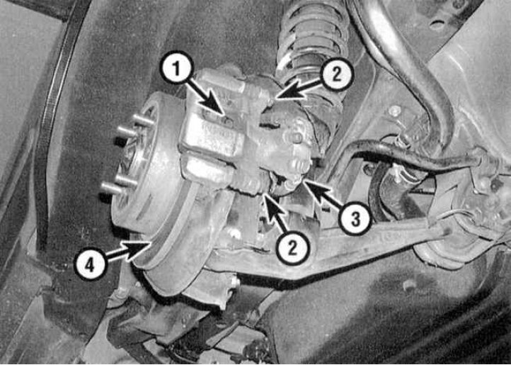


1 - Support; 2 - Caliper bolts; 3 - Brake hose; 4…

1 - Support; 2 - Caliper bolts; 3 - Brake hose; 4 - Brake disc


General information


All brake mechanisms have a self-adjusting design. At the same time, wear compensation of brake pads of disc mechanisms (front and back) is carried out automatically, whereas drum brake mechanisms are equipped with special adjustment devices, which are activated during braking, as well as when the parking brake is applied.

The dual design of the main brake cylinder (MBC) equipped with two separate reservoirs allows the hydraulic circuit to be divided into two circuits operating independently of each other. The latter means that if one of the circuits fails, the second continues to operate in the previous mode, ensuring adequate braking of the vehicle. The hydraulic circuits are arranged diagonally. Failure of any of the circuits naturally leads to a decrease in braking efficiency and is accompanied by the activation of a control lamp on the instrument panel when the foot brake pedal is depressed.

Master brake cylinder (MBC)


The brake master cylinder is mounted on the brake booster servo assembly, which is secured to the rear bulkhead of the engine compartment. A large hydraulic fluid reservoir, equipped with a plastic cover, is located on top of the cylinder. The reservoir is secured with a clamp.

As mentioned above, the master cylinder has a dual design, ensuring the operation of two independent hydraulic circuits. The fluid pressure in each circuit is pumped by an individual piston inside the master cylinder.

Regulator valve


In addition to the vacuum booster, a dual-circuit rear brake pressure regulator is included in the hydraulic drive of the brake system. The pressure regulator valve is installed on the rear bulkhead of the vehicle's engine compartment. On vehicles equipped with an anti-lock brake system (ABS), the valve is built into the hydraulic modulator unit located on the right side of the engine compartment.


The regulator valve is included in both circuits of the brake system and ensures pressure limitation in the hydraulic drive of the rear wheel brake mechanisms, preventing their premature blocking during sharp braking. The valve is triggered when the hydraulic pressure in the circuits reaches a certain value.

The regulator is not repairable and in case of failure must be replaced as an assembly.

Vacuum brake booster


The booster uses the vacuum created in the intake manifold to improve the efficiency of the brake system hydraulic drive. The vacuum booster servo is mounted on the rear bulkhead of the engine compartment.

Parking brake


The parking brake control lever is located in the passenger compartment. A single front drive cable is attached to the lever, which in turn is connected to a pair of rear cables. When the lever is cocked on models equipped with drum rear brake mechanisms, the rear cables pull the actuator levers attached to the brake shoe assemblies in the mechanisms of both rear wheels. In this case, the shoes are spread apart, pressing against the working surface of the drums. On models with disc brake mechanisms of the rear wheels, the actuator levers are attached to screw-type actuators in the caliper housings. The levers act on the caliper pistons, causing the pads to press against the brake discs.

Precautionary measures


When servicing vehicle brake components, there are some special precautions that should be taken:
  • a) Use only DOT 3 grade hydraulic fluid to fill the brake system;
  • b) The friction linings of the brake pads/shoes may contain asbestos, which is harmful to health. Avoid inhaling brake dust, and do not blow it off with compressed air. Use only special cleaning agents to wipe brake components;
  • c) Ensure that all required tolerances and tightening forces are observed. When servicing components, use only serviceable tools. If in doubt, seek help from specialists. Remember that proper functioning of the brakes is the key to traffic safety;
  • d) Never attempt to disconnect the brake system hydraulic drive components on models equipped with ABS. Remember that bleeding the hydraulic circuit on such vehicles is carried out using special equipment;
  • e) At the slightest sign of malfunction of the braking system, operation of the vehicle must be suspended!


[Material obtained from the website: HondaBook]
This article is available at: russian, bulgarian, belarusian, ukrainian, serbian, croatian, romanian, polish, slovak, hungarian
This information has been verified: Timofey Goryachev
Share with friends:
◀ Previous
Civic 6: Brake system
Next ▶

 
Brake system specifications
Anti-lock Brake System (ABS) — General Information and Error Codes
Replacement of brake pads of disc brake mechanisms
Removal, repair and installation of disc brake calipers
Checking the condition, removing and installing the brake disc
See also other articles from Honda manuals:
Brake system malfunctions Honda Accord 3 (1985-1989)
Bleeding the brake system Honda Fit 1 (2001-2008)
Features of operation of the brake system Honda CR-V 1 (1995-2001, petrol)
Brake system indicator wiring diagram Honda HR-V 1 (1998-2006, petrol)
Brake system — bleeding Honda Avancier 1 (1999-2003, petrol)
Link in different formats to this article
Comments and feedback from visitors
No comments yet


How much will 35 + 48 ?


Civic 8 (2005-2011) 
  • General information
  • Technical data
  • Governing bodies
  • Driving and maintenance
  • Power unit
  • Gasoline engines (L13A)
  • Gasoline engines (R18A)
  • Diesel engines (N22A)
  • Cooling and lubrication (L13A)
  • Cooling and lubrication (R18A)
  • Cooling and lubrication (N22A)
  • Injection system (gasoline)
  • Injection system (diesel)
  • Toxicity reduction system
  • Troubleshooting
  • Transmission
  • Clutch and drive shafts
  • Mechanical gearbox
  • Chassis and running gear
  • Suspension and wheels
  • Steering
  • Brake system
  • Body and interior
  • Exterior (external elements)
  • Doors, locks and windows
  • Electrical equipment
  • Equipment and devices
  • Headlights and lighting
  • Power devices
  • Electrical circuits
Civic 7 (2000-2005) 
  • General information
  • User manual
  • Maintenance
  • Power unit
  • Engines D15B and D17A
  • K20A Engines
  • Overhaul engine
  • Cooling system
  • Lubrication system
  • Fuel injection system
  • Toxicity reduction system
  • Engine electrical equipment
  • Transmission
  • Clutch
  • Manual gearbox
  • Automatic gearbox
  • Variator (CVT)
  • Drive shafts
  • Chassis and running gear
  • Car suspension
  • Steering
  • Brake system
  • Body and interior
  • Exterior (external elements)
  • Interior (internal elements)
  • Doors, locks and windows
  • Heater and air conditioner
  • Manual air conditioner
  • Automatic air conditioner
  • Security system
  • Electrical equipment
  • Equipment and devices
  • Headlights and lighting
  • Windscreen wipers
  • Audio system
  • Electrical diagrams
Civic 6 (1995-2000) 
  • General information
  • Introduction to guide
  • User manual
  • Maintenance
  • Power unit
  • Engine in car (Civic)
  • Engine in car (Integra)
  • Engine overhaul
  • Cooling and heating
  • Power and exhaust systems
  • Engine electrical equipment
  • Engine management systems
  • Transmission
  • Manual gearbox
  • Automatic transmission (AT/CVT)
  • Clutch and drive shafts
  • Chassis and running gear
  • Brake system
  • Car suspension
  • Steering
  • Body and interior
  • Exterior (external elements)
  • Interior (internal elements)
  • Doors, locks and windows
  • Electrical equipment
  • Equipment and devices
  • Electrical circuits
Civic 5 and 6 (1991-2000) 
  • Power unit
  • SOHC engines
  • DOHC engines
  • Engine overhaul
  • Cooling and lubrication system
  • Intake and exhaust system
  • Fuel injection system (SOHC)
  • Fuel injection system (DOHC)
  • Carburetor
  • Transmission
  • Clutch
  • Manual gearbox S4C
  • Manual gearbox S40
  • Automatic gearbox
  • Drive shafts
  • Chassis and running gear
  • Car suspension
  • Steering
  • Brake system
  • Body and interior
  • Body elements
  • Heater and air conditioner
  • Electrical equipment
  • Power devices
  • Equipment and instruments
  • Electrical circuits
Civic 3 and 4 (1983-1991) 
  • General information
  • Maintenance
  • Power unit
  • Engine in a car
  • Engine overhaul
  • Cooling system
  • Power and exhaust system
  • Engine electrical equipment
  • Emission control system
  • Transmission
  • Mechanical gearbox
  • Automatic gearbox
  • Clutch and drive shafts
  • Four-wheel drive
  • Chassis and running gear
  • Brake system
  • Car suspension
  • Steering
  • Body and interior
  • Body elements
  • Electrical equipment
  • Equipment and devices
  • Electrical circuits
HondaBook.ru © 2018–2026 • Mobile version • Sitemap: EN BG BY UA RS HR RO PL SK HU • Feedback • Driver Information • Search system • Bookmark
Accord 3 (1985-1989) • Accord 6 (1997-2002) • Civic 3 and 4 (1983-1991) • Civic 5 and 6 (1991-2000) • Civic 6 (1995-2000) • Civic 7 (2000-2005) • Civic 8 (2005-2011) • Fit 1 (2001-2008) • CR-V 1 (1995-2001) • CR-V 2 (2002-2006) • HR-V 1 (1998-2006) • Avancier 1 (1999-2003) •
 
This website uses cookies to ensure proper functioning. By clicking "OK," you agree.