Contents: Control ⇊ Replacement ⇊
Control
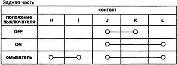
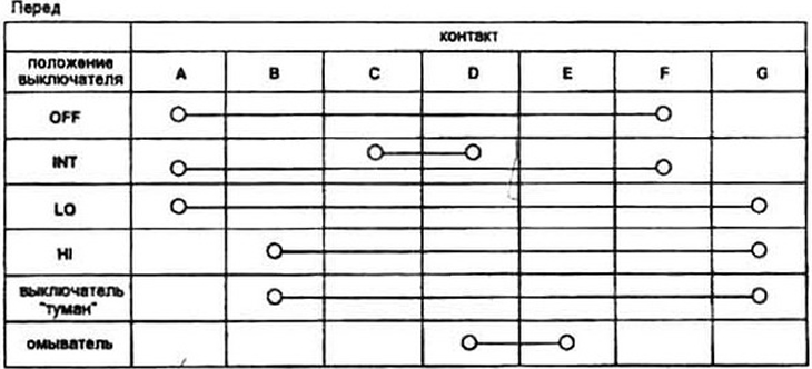
1. Disconnect the switch connectors (see steps 5-8).
2. Using an ohmmeter, check the conductivity between the connector contacts (see Fig. 6.2a, b). For example, on 1984-1987 models, with the switch in the hazard warning position and the turn signal in the neutral position, there should be continuity between the IG2 and RELEY IN terminals.
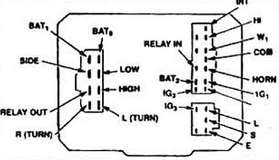
Fig. 6.2a Table of conductivity between contacts of a multifunctional switch (models 1984-1987.)
ON - on;
OFF - switched off;
HI - high speed;
LO - low speed;
INT - intermittent movement.
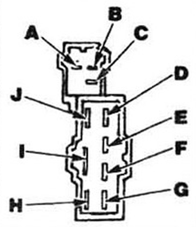
Fig. 6.2b Changes in models since 1988
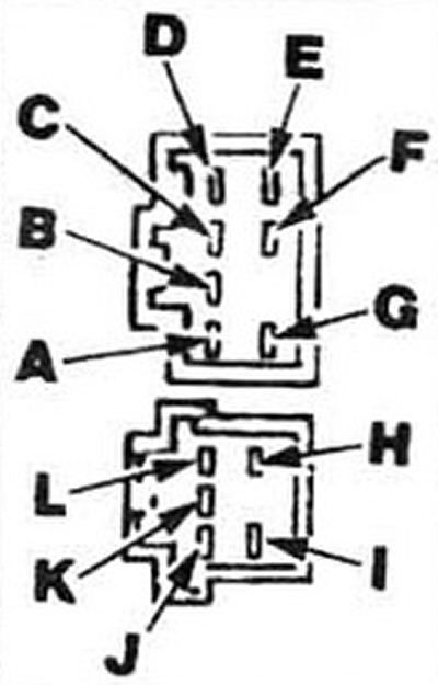
Fig. 6.2b Changes in models since 1988 (continuation)
ON - on;
OFF - off;
INT - intermittent motion;
LO - low speed;
HI - high speed.
3. Check all contacts in the sequence shown in Figures 6.2.
4. If a fault is detected, replace the switch.
Replacement
5. Disconnect the cable from the negative battery terminal.
6. Remove the steering wheel (see Chapter 10).
7. Remove the turn signal release coupling (if installed).
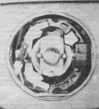
Fig. 6.7 Turn signal release clutch
8. Loosen the steering column cover screws and retaining ring. Remove the cover.
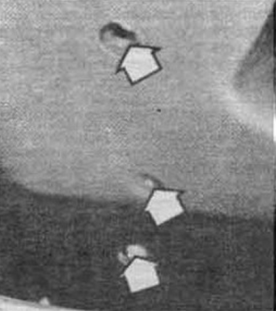
Fig. 6.8a Steering column cover mounting screws
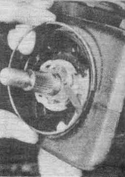
Fig. 6.86 Steering column cover retaining ring
9. Unscrew the two screws securing the switch.
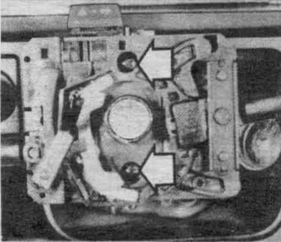
Fig. 6.9 Multi-function switch mounting screws
10. Disconnect and remove the switch.
11. Installation is carried out in the reverse order of removal.
Note: The turn signal release clutch is set to the "off" position.