
HondaBook.ru
Auto companies Volkswagen Auto companies Ford Auto companies Lada Auto companies Skoda Auto companies BMW Auto companies Mazda Auto companies Peugeot
English Русский
Български
Беларускі
Український
Српски
Hrvatski
Română
Polski
Slovenský
Magyar
Bookmark Contacts Sitemap   


Accord Civic Fit / Jazz CR-V HR-V Others Articles
Civic 3 and 4 (1983-1991) Civic 5 and 6 (1991-2000) Civic 6 (1995-2000) Civic 7 (2000-2005) Civic 8 (2005-2011)

Continuously Variable Transmission (CVT) — General Description (Honda Civic 7)

  • Main
  • Honda Civic
  • 7 (2000-2005)
  • Transmission
  • Variator (CVT)
  • Continuously Variable Transmission (CVT) — General Description
0
Contents: General information ⇊ Manual gear ratio change mode ⇊
Note:
  • The CVT type is stamped on an aluminum plate attached to the engine compartment bulkhead, in the line "TRANS/AXLE".
  • For the procedure for replacing the working fluid in the variator, see the chapter "Maintenance and general check and adjustment procedures".


General information


The variator consists of a continuously variable transmission (two composite pulleys and a metal belt), planetary gear (to ensure reverse movement), intermediate gear, main gear and control system elements.

The mechanical part of the variator consists of four parallel shafts (input shaft, continuously variable transmission drive pulley shaft, continuously variable transmission driven pulley shaft and final drive shaft). The input shaft is directly connected to the engine flywheel. The input shaft is connected to the drive pulley shaft via a planetary gear. The driven pulley shaft also has a starting clutch that starts the car and the drive gear of the intermediate gear. The driven gear of the intermediate gear is rigidly connected to the drive gear of the main gear.

To control the operation of the planetary gear set of the variator, a forward clutch and a reverse brake are used.

The electrical part of the variator control system consists of three parts:
  • a) Sensors that determine the vehicle's condition parameters and transmit this data to the electronic control unit.
  • b) The control unit, which determines the gear ratio of the continuously variable transmission, changes the direction of movement of the vehicle depending on the selected range.
  • c) The actuator, which consists of electromagnetic valves.

The control unit uses electromagnetic valves to change the distance between the pulley cheeks, thus changing the gear ratio.


The pressure control solenoid valve varies the pressure (HLC) supplied to the pressure distribution control valve between the pulleys.

The electromagnetic valve for pressure distribution between pulleys (SH) distributes the pressure of the working fluid supplied to the driving and driven pulleys.

The starter clutch control solenoid valve changes the pressure supplied to the starter clutch (SC), which changes depending on the degree of opening of the throttle valve.

Manual gear ratio change mode


Some modifications have a manual mode for changing the variator gear ratio.

In this mode, there are seven fixed positions of the variator pulleys, corresponding to the gears of a conventional gearbox. The seven "gears" are changed by the driver using the upshift and downshift switches on the steering wheel. The selected gear ratio number is displayed on the instrument cluster (range from "1" to "7")
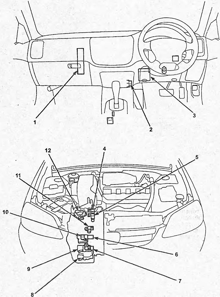
Layout of continuously variable transmission…

Layout of continuously variable transmission (CVT) components (sedan). 1 - engine and variator control unit, 2 - diagnostic connector, 3 - mounting block in the passenger compartment, 4 - speed sensor No.1, 5 - speed sensor No.2, 6 - electromagnetic pressure control valve, 7 - drive pulley speed sensor, 8 - electromagnetic valve for pressure distribution between pulleys, 9 - electromagnetic valve for controlling the starting clutch, 10 - electromagnetic start prohibition valve, 11 - driven pulley speed sensor, 12 - selector position sensor.
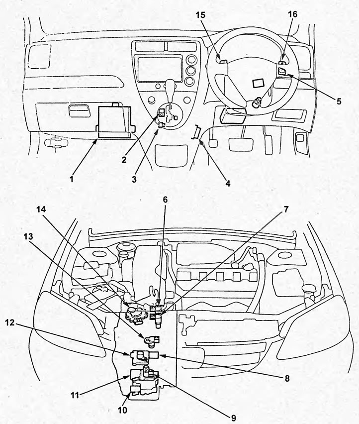


Layout of continuously variable transmission…

Layout of continuously variable transmission (CVT) components (hatchback). 1 - engine and variator control unit, 2 - selector lock electromagnetic valve, 3 - selector "S" position sensor, 4 - diagnostic connector, 5* - manual shift mode switch, 6 - speed sensor No.1, 7 - speed sensor No.2, 8 - pressure control electromagnetic valve, 9 - drive pulley speed sensor, 10 - pulley pressure distribution electromagnetic valve, 11 - starting clutch control electromagnetic valve, 12 - start inhibit electromagnetic valve, 13 - driven pulley speed sensor, 14 - selector position sensor, 15* - downshift switch in manual shift mode, 16* - upshift switch in manual shift mode. Note: * - models with manual switching mode.


[The article was taken from the website «www.hondabook.ru»]
This article is available at: russian, bulgarian, belarusian, ukrainian, serbian, croatian, romanian, polish, slovak, hungarian
This information has been verified: Yaroslav Shiryaev
Share with friends:
◀ Previous
Civic 7: Variator (CVT)
Next ▶

 
Variator (CVT) — diagnostics
Self-diagnosis system
Checking mechanical systems
Road test
Filter replacement
See also other articles from Honda manuals:
Overhaul of a manual transmission — general information Honda Accord 6 (1997-2002)
Continuously Variable Transmission (CVT) — General Description Honda Fit 1 (2001-2008)
Manual transmission oil Honda CR-V 1 (1995-2001, petrol)
Gear shift lever (models with manual transmission) Honda HR-V 1 (1998-2006, petrol)
Selector lever, automatic transmission Honda Avancier 1 (1999-2003, petrol)
Link in different formats to this article
Comments and feedback from visitors
No comments yet


How much will 38 + 31 ?


Civic 8 (2005-2011) 
  • General information
  • Technical data
  • Governing bodies
  • Driving and maintenance
  • Power unit
  • Gasoline engines (L13A)
  • Gasoline engines (R18A)
  • Diesel engines (N22A)
  • Cooling and lubrication (L13A)
  • Cooling and lubrication (R18A)
  • Cooling and lubrication (N22A)
  • Injection system (gasoline)
  • Injection system (diesel)
  • Toxicity reduction system
  • Troubleshooting
  • Transmission
  • Clutch and drive shafts
  • Mechanical gearbox
  • Chassis and running gear
  • Suspension and wheels
  • Steering
  • Brake system
  • Body and interior
  • Exterior (external elements)
  • Doors, locks and windows
  • Electrical equipment
  • Equipment and devices
  • Headlights and lighting
  • Power devices
  • Electrical circuits
Civic 7 (2000-2005) 
  • General information
  • User manual
  • Maintenance
  • Power unit
  • Engines D15B and D17A
  • K20A Engines
  • Overhaul engine
  • Cooling system
  • Lubrication system
  • Fuel injection system
  • Toxicity reduction system
  • Engine electrical equipment
  • Transmission
  • Clutch
  • Manual gearbox
  • Automatic gearbox
  • Variator (CVT)
  • Drive shafts
  • Chassis and running gear
  • Car suspension
  • Steering
  • Brake system
  • Body and interior
  • Exterior (external elements)
  • Interior (internal elements)
  • Doors, locks and windows
  • Heater and air conditioner
  • Manual air conditioner
  • Automatic air conditioner
  • Security system
  • Electrical equipment
  • Equipment and devices
  • Headlights and lighting
  • Windscreen wipers
  • Audio system
  • Electrical diagrams
Civic 6 (1995-2000) 
  • General information
  • Introduction to guide
  • User manual
  • Maintenance
  • Power unit
  • Engine in car (Civic)
  • Engine in car (Integra)
  • Engine overhaul
  • Cooling and heating
  • Power and exhaust systems
  • Engine electrical equipment
  • Engine management systems
  • Transmission
  • Manual gearbox
  • Automatic transmission (AT/CVT)
  • Clutch and drive shafts
  • Chassis and running gear
  • Brake system
  • Car suspension
  • Steering
  • Body and interior
  • Exterior (external elements)
  • Interior (internal elements)
  • Doors, locks and windows
  • Electrical equipment
  • Equipment and devices
  • Electrical circuits
Civic 5 and 6 (1991-2000) 
  • Power unit
  • SOHC engines
  • DOHC engines
  • Engine overhaul
  • Cooling and lubrication system
  • Intake and exhaust system
  • Fuel injection system (SOHC)
  • Fuel injection system (DOHC)
  • Carburetor
  • Transmission
  • Clutch
  • Manual gearbox S4C
  • Manual gearbox S40
  • Automatic gearbox
  • Drive shafts
  • Chassis and running gear
  • Car suspension
  • Steering
  • Brake system
  • Body and interior
  • Body elements
  • Heater and air conditioner
  • Electrical equipment
  • Power devices
  • Equipment and instruments
  • Electrical circuits
Civic 3 and 4 (1983-1991) 
  • General information
  • Maintenance
  • Power unit
  • Engine in a car
  • Engine overhaul
  • Cooling system
  • Power and exhaust system
  • Engine electrical equipment
  • Emission control system
  • Transmission
  • Mechanical gearbox
  • Automatic gearbox
  • Clutch and drive shafts
  • Four-wheel drive
  • Chassis and running gear
  • Brake system
  • Car suspension
  • Steering
  • Body and interior
  • Body elements
  • Electrical equipment
  • Equipment and devices
  • Electrical circuits
HondaBook.ru © 2018–2026 • Mobile version • Sitemap: EN BG BY UA RS HR RO PL SK HU • Feedback • Driver Information • Search system • Bookmark
Accord 3 (1985-1989) • Accord 6 (1997-2002) • Civic 3 and 4 (1983-1991) • Civic 5 and 6 (1991-2000) • Civic 6 (1995-2000) • Civic 7 (2000-2005) • Civic 8 (2005-2011) • Fit 1 (2001-2008) • CR-V 1 (1995-2001) • CR-V 2 (2002-2006) • HR-V 1 (1998-2006) • Avancier 1 (1999-2003) •
 
This website uses cookies to ensure proper functioning. By clicking "OK," you agree.