HondaBook.ru
Auto companies Volkswagen Auto companies Ford Auto companies Lada Auto companies Skoda Auto companies BMW Auto companies Mazda Auto companies Peugeot
English Русский
Български
Беларускі
Український
Српски
Hrvatski
Română
Polski
Slovenský
Magyar
Bookmark Contacts Sitemap   


Accord Civic Fit / Jazz CR-V HR-V Others Articles
Civic 3 and 4 (1983-1991) Civic 5 and 6 (1991-2000) Civic 6 (1995-2000) Civic 7 (2000-2005) Civic 8 (2005-2011)

Checking the balance mechanism (K20A models with a balance shaft block) (Honda Civic 7)

  • Main
  • Honda Civic
  • 7 (2000-2005)
  • Power unit
  • Overhaul engine
  • Checking the balance mechanism (K20A models with a balance shaft block)
0
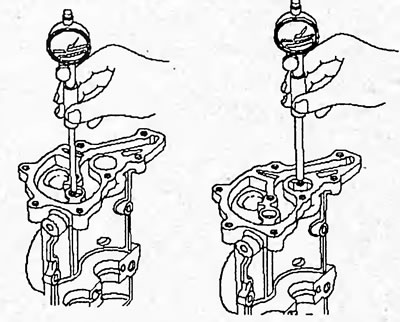
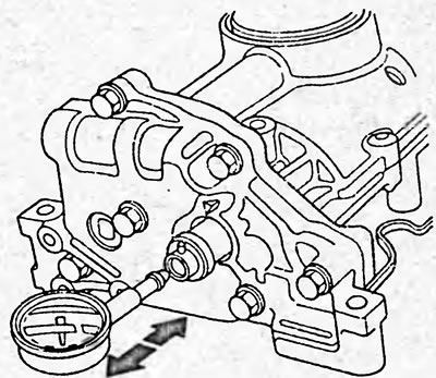
1. Check the axial clearance of the balance shafts.

1. Check the axial clearance of the balance…


Use a dial indicator to measure the axial clearance while moving the balance shafts back and forth.

Axial clearance of balance shafts:
  • nominal - 0.070 -0.135 mm
  • maximum allowable - 0.15 mm

If the axial clearance is greater than the maximum allowable, replace the balance shaft thrust washer.

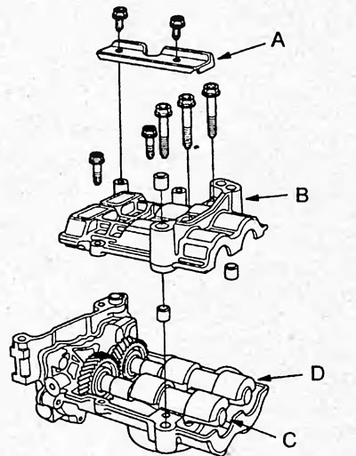
2. Loosen the mounting bolts, remove the oil separator plate (A), the balance mechanism housing cover (B) and remove the left balance shaft (D) and the right balance shaft (C).

Note: Do not damage the bearing surface of the balance shafts.

Note: Do not damage the bearing surface of the…


3. Check the balance shafts.

a) Measure the inner diameter of the balance shaft bearing.

Nominal diameter:
  • left balance shaft - 20,000 - 20,020 mm
  • right balance shaft - 24.000 - 24.020 mm

Maximum diameter:


  • left balance shaft - 20.03 mm
  • right balance shaft - 24.03 mm

right balance shaft - 24.03 mm


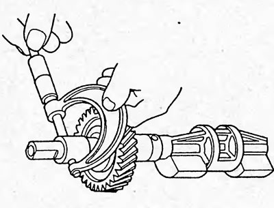
b) Measure the diameter of journals No.1 of the balance shafts.

Nominal diameter:
  • left balance shaft - 19.938 - 19.950 mm
  • right balance shaft - 23.938 - 23.950 mm

Minimum diameter:
  • left balance shaft - 19.92 mm
  • right balance shaft - 23.92 mm

right balance shaft - 23.92 mm


c) Clean the journals No.2 of the balance shafts and the inner surface of the bearing.

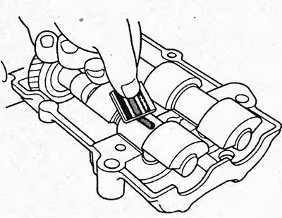
d) Place a plastic gauge on each balance shaft journal.

d) Install the balance mechanism housing cover and tighten the mounting bolts.

Note: Do not rotate the balance shafts during inspection.


Tightening torque: 27 Nm

e) Remove the balance mechanism housing cover and measure the width of the flattened plastic gauge, determining the value of the radial oil clearance.


  • Nominal clearance - 0.060 -0.120 mm
  • Maximum gap - 0.15 mm

Maximum gap - 0.15 mm

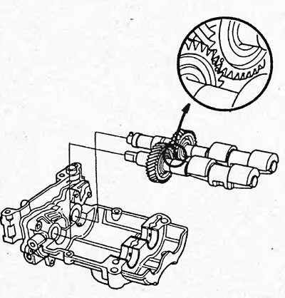
4. Engage the balance shaft gears so that the mark on the right balance shaft gear is in the middle between the two marks on the left balance shaft gear and install the balance shafts into the balance mechanism housing.
4. Engage the balance shaft gears so that the…


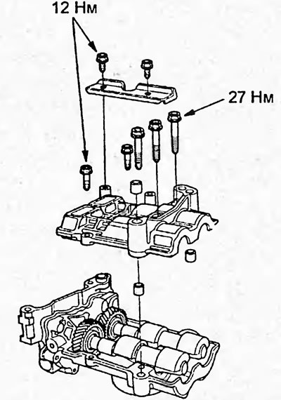
5. Apply a layer of engine oil to the threads of the balancer housing cover mounting bolts, install the cover and tighten the mounting bolts.
5. Apply a layer of engine oil to the threads of…


Assembly


Note:
  • Thoroughly clean all parts to be assembled.
  • Before assembly, lubricate all parts that form rotating or sliding units with fresh engine oil.
  • Replace all gaskets, O-rings and seals with new ones.


1. Install the main and connecting rod bearing shells.


2. Install the upper thrust half rings into the bed of main bearing block No.4 with the lubrication grooves facing outward.
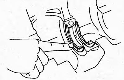
2. Install the upper thrust half rings into the…


3. Place the crankshaft into the cylinder block, holding it so that connecting rod journals No.2 and No.3 are at the top.

4. (K20A) Apply a layer of sealant to the crankshaft main bearing cap as shown in the figure.
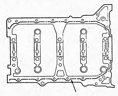
4. (K20A) Apply a layer of sealant to the…


5. Install the main bearing caps and thrust washers.

A. Install the main bearing caps.
  • a) Install two thrust half rings on bearing cover No.4, orienting the oil grooves outward.
  • b) Install the main bearing cap.
  • c) Using a plastic-faced hammer, tap the bearing caps until they fit snugly.
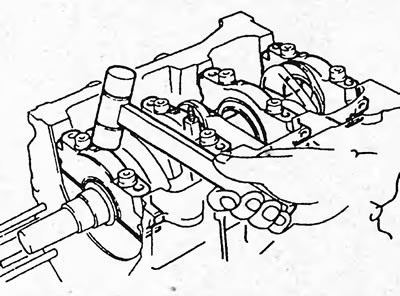
D15B, D17A.
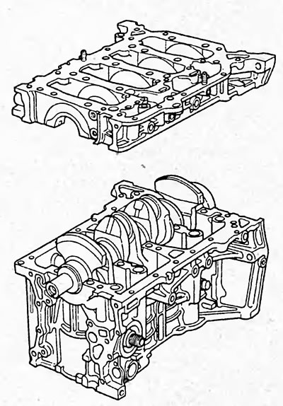
D15B, D17A.


K20A.

K20A.

  • d) Apply a thin layer of engine oil to the threads and under the heads of the main bearing cap bolts.

B. Tighten the main bearing cap bolts.
  • Tighten the main bearing cap bolts.

Tighten the main bearing cap bolts.


Tightening torque:

D15B — 45 Nm

D17A:
  • 1 step - 25 Nm
  • step 2 - 51 Nm

K20A:
  • 1 step - 29 Nm
  • step 2 - 60°

If the specified torque is not achieved when tightening any bolt, replace the bolt.

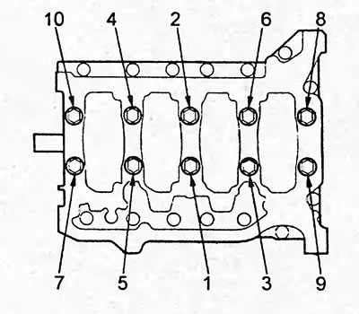
6. (K20A) Tighten the main bearing cap bolts (8 mm) in the sequence shown in the figure.

Tightening torque: 22 Nm
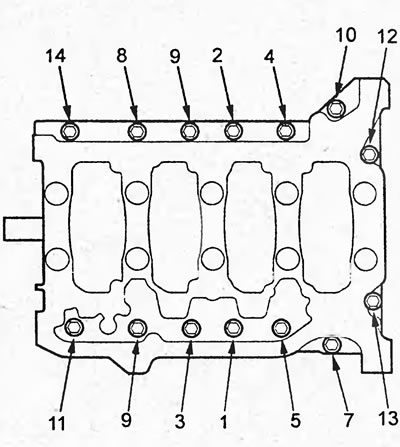
Tightening torque: 22 Nm


7. Make sure the crankshaft rotates smoothly.


8. Using a dial indicator, measure the crankshaft axial clearance while moving the crankshaft with a screwdriver (see above).

9. Install the piston and connecting rod assembly.

a) Install the piston sets into the cylinders according to their numbers, orienting the marks (B) on the pistons towards the front of the engine. Install rubber insulators (A) on the connecting rod bolt threads.
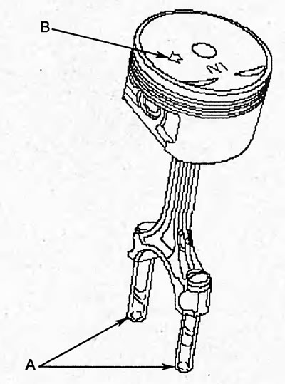
D15B, D17A.
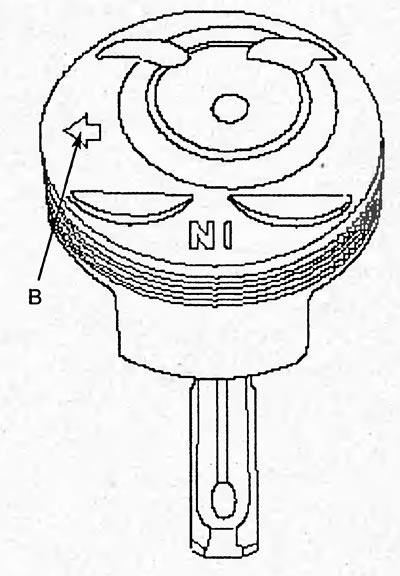
D15B, D17A.


K20A.

K20A.


b) Using light taps, drive the piston into the cylinder.
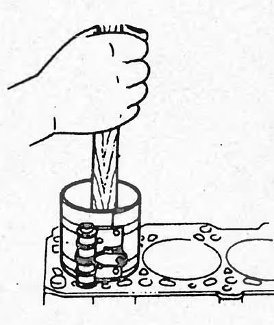
b) Using light taps, drive the piston into the…


10. Install the connecting rod lower head caps.
  • a) Install the connecting rod lower head caps onto the connecting rods.
  • b) Check that the numbering of the connecting rod bearing caps and connecting rods matches.
  • c) Apply engine oil to the threads of the mounting bolts.
  • d) Tighten the nuts (bolts) securing the connecting rod lower head caps evenly and alternately.

Tightening torque:

D15B, D17A — 32 Nm

K20A (models with rocker blocks of types 1 and 2):
  • 1 step - 20 Nm
  • step 2 - 90°

K20A (models with type 3 rocker block):
  • 1 step - 29 Nm
  • step 2 - 90°

If any bolt is not tightened to the specified torque, replace it.

11. Using a dial indicator, measure the end play as the connecting rod moves back and forth (see above).
This article is available at: russian, bulgarian, belarusian, ukrainian, serbian, croatian, romanian, polish, slovak, hungarian
This information has been verified: Yaroslav Shiryaev
Share with friends:
◀ Previous
Civic 7: Overhaul engine
Next ▶

Cylinder block — piston-connecting rod assembly (K20A)
Cylinder Block — Piston-Connecting Rod Assembly (D15B, D17A)
Cylinder Block — Crankshaft Check and Repair
Cylinder Block — Checking the Condition of the Piston and Connecting Rod
Cylinder block — disassembly of the piston-connecting rod unit (K20A)
 
See also other articles from Honda manuals:
Removal, condition check and installation of gear wheels and balance… Honda Accord 6 (1997-2002)
Checking the VTEC (LISA) rocker shaft Honda Fit 1 (2001-2008)
Balance Shaft (4-cylinder Odyssey models) Honda CR-V 1 (1995-2001, petrol)
Cylinder Block — Checking and Honing Honda HR-V 1 (1998-2006, petrol)
Checking the balance shaft belt Honda Avancier 1 (1999-2003, petrol)
Link in different formats to this article
Comments and feedback from visitors
No comments yet


How much will 47 + 11 ?


Civic 8 (2005-2011) 
  • General information
  • Technical data
  • Governing bodies
  • Driving and maintenance
  • Power unit
  • Gasoline engines (L13A)
  • Gasoline engines (R18A)
  • Diesel engines (N22A)
  • Cooling and lubrication (L13A)
  • Cooling and lubrication (R18A)
  • Cooling and lubrication (N22A)
  • Injection system (gasoline)
  • Injection system (diesel)
  • Toxicity reduction system
  • Troubleshooting
  • Transmission
  • Clutch and drive shafts
  • Mechanical gearbox
  • Chassis and running gear
  • Suspension and wheels
  • Steering
  • Brake system
  • Body and interior
  • Exterior (external elements)
  • Doors, locks and windows
  • Electrical equipment
  • Equipment and devices
  • Headlights and lighting
  • Power devices
  • Electrical circuits
Civic 7 (2000-2005) 
  • General information
  • User manual
  • Maintenance
  • Power unit
  • Engines D15B and D17A
  • K20A Engines
  • Overhaul engine
  • Cooling system
  • Lubrication system
  • Fuel injection system
  • Toxicity reduction system
  • Engine electrical equipment
  • Transmission
  • Clutch
  • Manual gearbox
  • Automatic gearbox
  • Variator (CVT)
  • Drive shafts
  • Chassis and running gear
  • Car suspension
  • Steering
  • Brake system
  • Body and interior
  • Exterior (external elements)
  • Interior (internal elements)
  • Doors, locks and windows
  • Heater and air conditioner
  • Manual air conditioner
  • Automatic air conditioner
  • Security system
  • Electrical equipment
  • Equipment and devices
  • Headlights and lighting
  • Windscreen wipers
  • Audio system
  • Electrical diagrams
Civic 6 (1995-2000) 
  • General information
  • Introduction to guide
  • User manual
  • Maintenance
  • Power unit
  • Engine in car (Civic)
  • Engine in car (Integra)
  • Engine overhaul
  • Cooling and heating
  • Power and exhaust systems
  • Engine electrical equipment
  • Engine management systems
  • Transmission
  • Manual gearbox
  • Automatic transmission (AT/CVT)
  • Clutch and drive shafts
  • Chassis and running gear
  • Brake system
  • Car suspension
  • Steering
  • Body and interior
  • Exterior (external elements)
  • Interior (internal elements)
  • Doors, locks and windows
  • Electrical equipment
  • Equipment and devices
  • Electrical circuits
Civic 5 and 6 (1991-2000) 
  • Power unit
  • SOHC engines
  • DOHC engines
  • Engine overhaul
  • Cooling and lubrication system
  • Intake and exhaust system
  • Fuel injection system (SOHC)
  • Fuel injection system (DOHC)
  • Carburetor
  • Transmission
  • Clutch
  • Manual gearbox S4C
  • Manual gearbox S40
  • Automatic gearbox
  • Drive shafts
  • Chassis and running gear
  • Car suspension
  • Steering
  • Brake system
  • Body and interior
  • Body elements
  • Heater and air conditioner
  • Electrical equipment
  • Power devices
  • Equipment and instruments
  • Electrical circuits
Civic 3 and 4 (1983-1991) 
  • General information
  • Maintenance
  • Power unit
  • Engine in a car
  • Engine overhaul
  • Cooling system
  • Power and exhaust system
  • Engine electrical equipment
  • Emission control system
  • Transmission
  • Mechanical gearbox
  • Automatic gearbox
  • Clutch and drive shafts
  • Four-wheel drive
  • Chassis and running gear
  • Brake system
  • Car suspension
  • Steering
  • Body and interior
  • Body elements
  • Electrical equipment
  • Equipment and devices
  • Electrical circuits
HondaBook.ru © 2018–2026 • Mobile version • Sitemap: EN BG BY UA RS HR RO PL SK HU • Feedback • Driver Information • Search system • Bookmark
Accord 3 (1985-1989) • Accord 6 (1997-2002) • Civic 3 and 4 (1983-1991) • Civic 5 and 6 (1991-2000) • Civic 6 (1995-2000) • Civic 7 (2000-2005) • Civic 8 (2005-2011) • Fit 1 (2001-2008) • CR-V 1 (1995-2001) • CR-V 2 (2002-2006) • HR-V 1 (1998-2006) • Avancier 1 (1999-2003) •
 
This website uses cookies to ensure proper functioning. By clicking "OK," you agree.