
Contents: Removal ⇊ Disassembly, inspection, cleaning…⇊ Checking VTC and VTEC systems ⇊ Disassembling and assembling the…⇊ Installation ⇊ Replacing crankshaft seals ⇊
Removal
Note:
- To avoid warping the cylinder head, do not remove it when the coolant temperature is above 38°C.
- Label all wires and hoses before disconnecting. Make sure they do not come into contact with other wires, hoses or components.
1. Before carrying out any work, turn off the vehicle's security system.
2. Disconnect the cable from the negative terminal of the battery.
3. Drain the coolant.
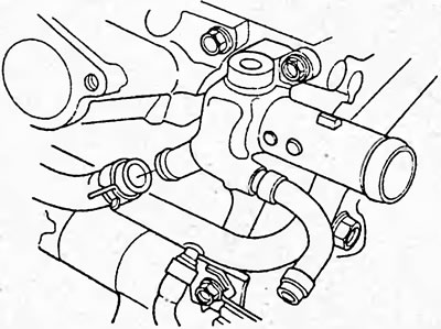
4. Disconnect the cooling system bypass hoses.
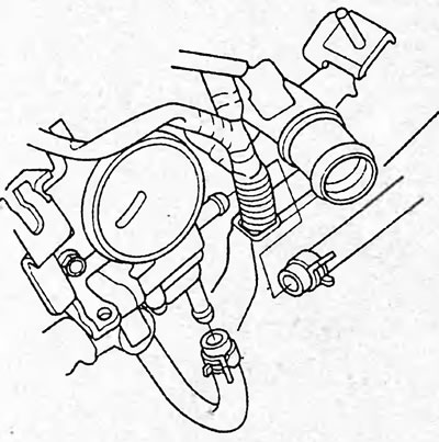
Models with 1 and 2 types of rocker blocks.
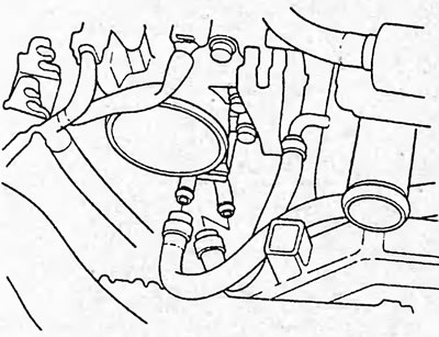
Models with 3 types of rocker blocks.
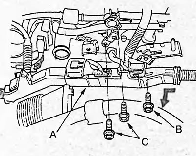
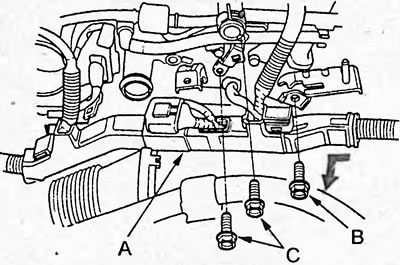
5. Remove the wire harness protector (A), then remove the connecting pipe mounting bolt (B) and the vacuum booster pipe mounting bolts (C).
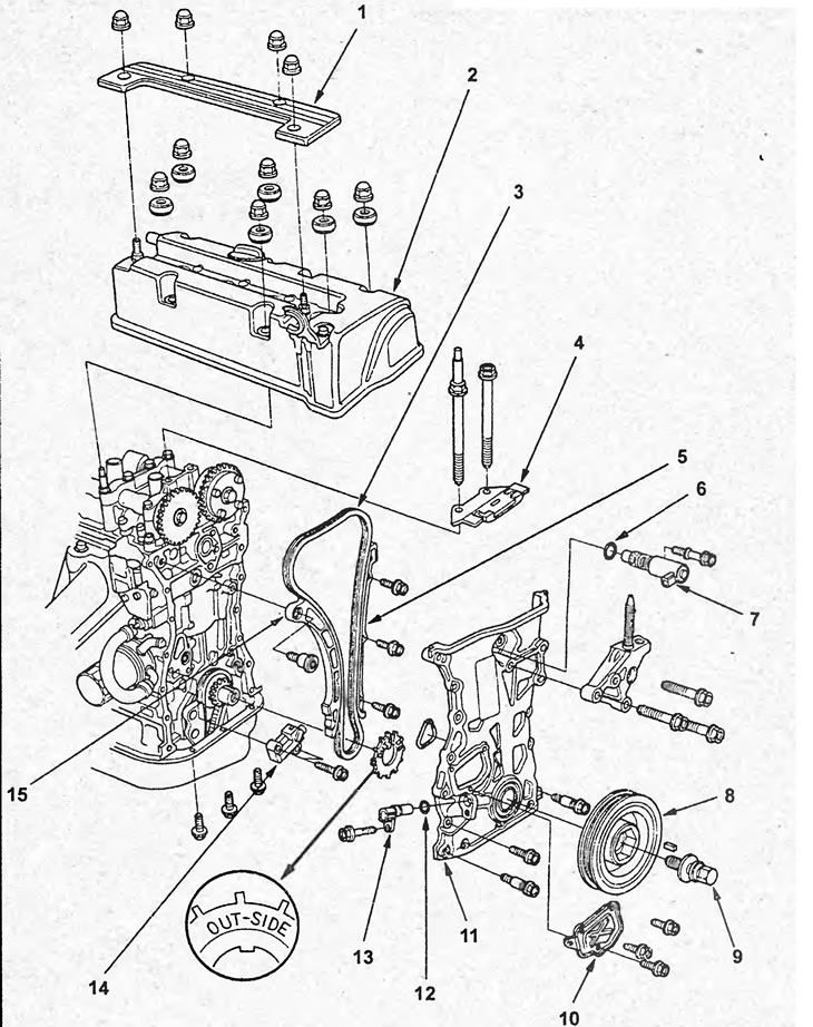
Removal and installation the cylinder head (step 1). 1 - protective cover, 2 - cylinder head cover, 3 - timing chain, 4 - timing chain damper, 5 - timing chain guide, 6, 12 - sealing ring, 7 - variable valve timing (VTC) valve, 8 - crankshaft pulley, 9 - crankshaft pulley mounting bolt, 10 - service cover, 11 - timing chain cover, 13 - crankshaft position sensor, 14 - timing chain tensioner, 15 - timing chain tensioner guide.
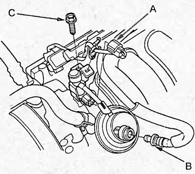
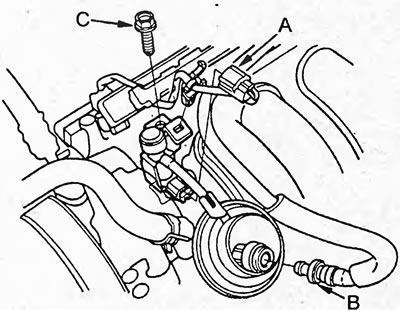
6. (Models with 1 and 2 type rocker block) Disconnect the connector (A) of the bypass solenoid valve, the hose (B) from the positive crankcase ventilation valve and unscrew the bolt (C) securing the solenoid valve.
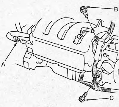
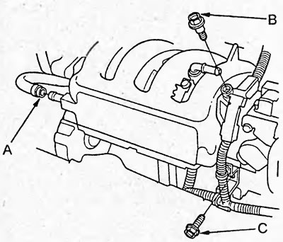
7. (Models with 3 type rocker block) Disconnect the positive crankcase ventilation hose (A) and remove the bolts (B) and (C) securing the retainer and the wiring harness bracket.
8. Disconnect the connectors shown below and remove the wiring harness by detaching the clips and brackets:
- Four injector connectors.
- Manifold Absolute Pressure Sensor Connector.
- Throttle position sensor connector.
- Idle speed control valve connector.
- Fuel vapor accumulator solenoid valve connector.
- Coolant temperature sensor connector.
- Camshaft Position Sensor (VTC) Connector.
- Camshaft position sensor connector.
- Oil pressure sensor connector.
- Variable Valve Timing and Elevation Control (VTEC) valve connector.
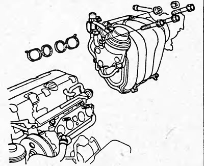
9. (Models with 1 and 2 type rocker block) Remove the intake manifold.
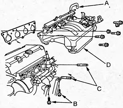
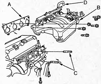
10. (Models with 3 type rocker block) Disconnect the hose (A) from the additional air supply system valve to the injectors and remove the intake manifold bracket by unscrewing the mounting bolts (B). Remove the studs (C) and the intake manifold (D).
11. Remove the cooling system bypass hose.
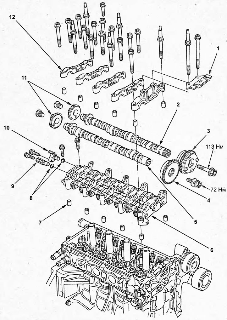
Removal and installation the cylinder head (step 2). 1 - Timing chain damper, 2 - Intake camshaft, 3 - Variable valve timing (VTC) clutch, 4 - Exhaust camshaft sprocket, 5 - Exhaust camshaft, 6 - VTEC rocker arm assembly, 7 - Dowel pins, 8 - O-ring, 9 - VTC camshaft position sensor, 10 - VTC camshaft position sensor, 11 - VTC camshaft position sensor rotors, 12 - Camshaft bearing caps.
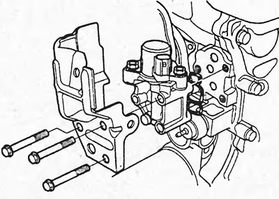
12. Remove the valve of the valve timing and lift Height adjustment system (VTEC).
13. (Models with 1 and 2 type rocker block) Remove the exhaust manifold heat shield (A), exhaust manifold bracket (B) and remove the exhaust manifold (C) by unscrewing the mounting bolts.
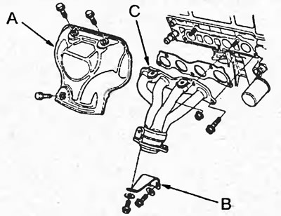
14. (Models with 3 type rocker block) Remove the exhaust manifold heat shield (A) and remove the exhaust manifold (B) by unscrewing the mounting bolts.
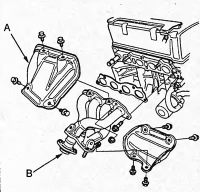
15. Remove the cylinder head cover.
16. Remove the timing chain.
17. Remove the VTEC rocker arm assembly and camshafts.
a) Loosen the adjusting nuts (A).
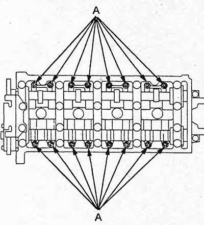
b) Loosen the camshaft bearing cap mounting bolts in 2 passes in the sequence shown in the figure.
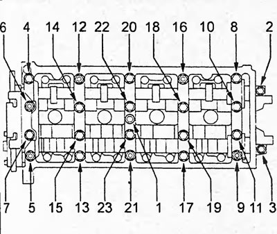
c) Remove the timing chain guide, camshaft bearing caps and camshafts.
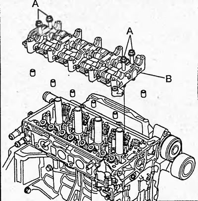
d) Install the bolts (A) into the VTEC rocker arm assembly and remove the VTEC rocker arm assembly (B).
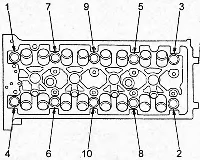
18. Remove the cylinder head mounting bolts. To prevent warping of the cylinder head, remove the bolts one by one by 1/3 of a turn per pass in the sequence shown in the figure.
19. Remove the cylinder head.
Disassembly, inspection, cleaning and repair of the cylinder head
The procedures for disassembling, checking, cleaning, repairing and assembling the cylinder head components are discussed in the chapter "Engine - General Repair Procedures".
Checking VTC and VTEC systems
1. Checking the variable valve timing (VTC) clutch.
a) Remove the intake camshaft.
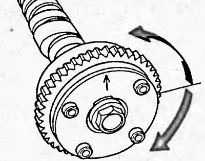
b) Check that the coupling is locked by turning the coupling clockwise and counterclockwise. If the coupling rotates, replace the coupling.
c) Install plugs in the channels for controlling the advance (A) and retard (B).
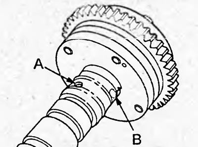
d) Open one of the advance control holes.
d) Apply compressed air into the open hole by inserting the special tool as shown in the figure.
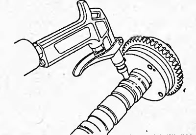
e) Check the smooth rotation of the coupling; if the coupling does not rotate smoothly, replace the coupling.
2. (Models with 1 type of rocker block) Checking the VTEC rocker arm assembly.
Note: The test is performed on the vehicle. Before testing, set the piston of cylinder #1 to TDC.
a) Check that the primary intake rocker arm (A) moves independently of the secondary intake rocker arm (B).
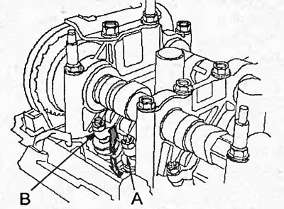
If the primary rocker arm does not move freely, remove the primary rocker arm and secondary rocker arm assembly and check that the timing pin rotates smoothly. Replace the primary and secondary rocker arm assemblies if necessary.
b) Check all rocker arms in the manner described above.
c) Check the thermal clearances in the valve drive. Adjust the clearances if necessary.
d) Loosen and remove the plug bolt (A) from the pressure relief hole and connect the special tool (B) as shown in the figure.
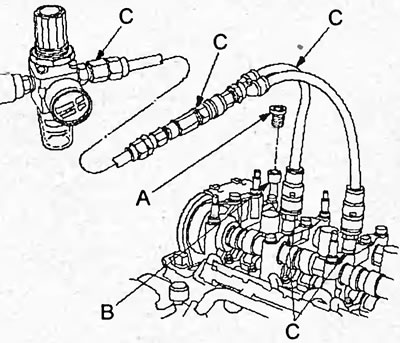
d) Unscrew the bolts securing the camshaft bearing caps No.2 and No.3 and connect the special tools (C) as shown in the figure above.
e) Apply a pressure of 290 kPa.
Note: If the timing pins do not rotate after increasing the pressure, turn the crankshaft clockwise to make the main and sub rocker arms start moving.
g) Move the primary rocker arm (A) of cylinder No.1. The primary and secondary (B) rocker arms should move together.
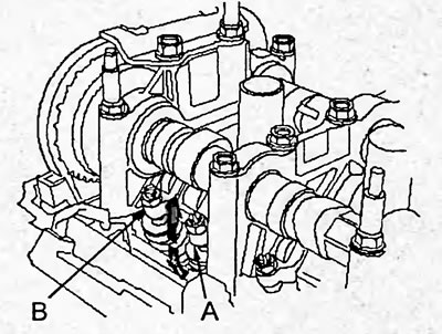
If the primary rocker arm does not move freely, remove the primary rocker arm and secondary rocker arm assembly and check that the timing pin rotates smoothly. Replace the primary and secondary rocker arm assemblies if necessary.
h) Remove the special tools and install the plug bolt and camshafts.
3. (Models with 2 and 3 type rocker blocks) Checking the VTEC rocker arm assembly.
Note: The test is performed on the vehicle. Before testing, set the piston of cylinder #1 to TDC.
a) Check that the secondary intake rocker arm (A) moves independently of the middle intake rocker arm (B).
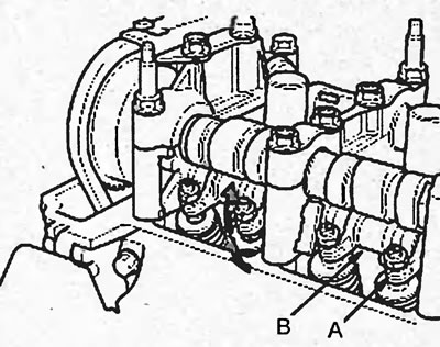
If the secondary rocker arm does not move freely, remove the primary, secondary and intermediate rocker arm assemblies and check that the timing pin rotates smoothly. Replace the rocker arm assemblies if necessary.
b) Check all rocker arms in the manner described above.
c) Check the thermal clearances in the valve drive. Adjust the clearances if necessary.
d) Loosen and remove the plug bolt (A) from the pressure relief hole and connect the special tool (B) as shown in the figure.
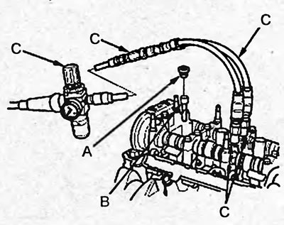
d) Unscrew the bolts securing cover No.3 of the camshaft bearings and connect the special tools (C) as shown in the figure above.
e) Apply a pressure of 290 kPa.
Note: If the timing pins do not rotate after increasing the pressure, turn the crankshaft clockwise to make the main and sub rocker arms start moving.
g) Move the secondary rocker arm (A) of cylinder No.1. The secondary, middle (B) and primary (C) rocker arms should move together.
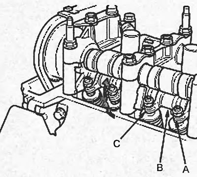
If the primary and secondary rocker arms do not move with the secondary, remove the rocker arm assemblies and check that the timing pin rotates smoothly. Replace the rocker arm assemblies if necessary.
h) Remove the special tools and install the plug bolt and camshafts.
Tightening torque:
- bolt plug - 20 Nm
- cover mounting bolts - 22 Nm
Disassembling and assembling the VTEC rocker arm unit
Note:
- See the pictures "VTEC system rocker arm block".
- When disassembling the VTEC rocker arm assembly, stack the parts in the order they were removed for subsequent installation.
- When removing the rocker arms, do not loosen the camshaft bearing cap mounting bolts.
- Before assembly, clean all parts with solvent and apply a layer of grease to the contact surfaces.
- After assembling the rocker arms, secure them with a rubber band.
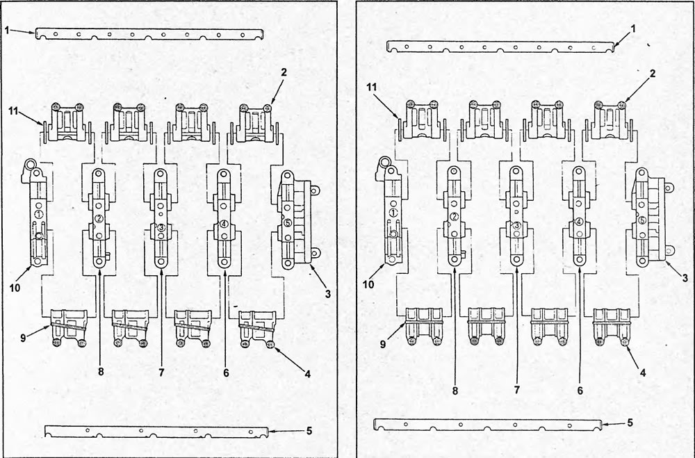
Note: The cylinder head of this engine type can be equipped with three types of VTEC rocker arm units. They differ in the installed rocker arms (see the pictures "VTEC Rocker Arm Unit").
Installation
The cylinder head is installed in the reverse order of removal.
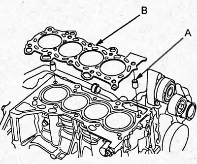
1. Clean the surface of the cylinder head and block.
2. Install a new cylinder head gasket (B) and dowel pins (A) onto the cylinder block.
Note: Always use a new cylinder head gasket.
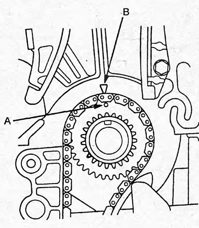
3. Align the mark (A) on the crankshaft sprocket with the reference mark (B) on the cylinder block.
4. Place the cylinder head on the cylinder block.
5. Apply fresh engine oil to the threads and under the bolt heads.
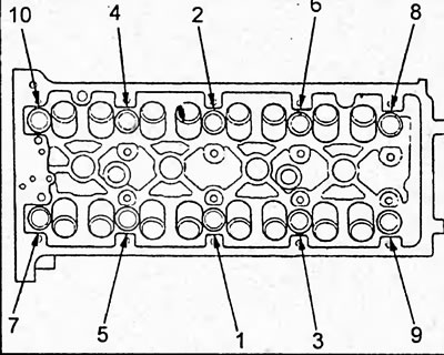
6. Tighten the cylinder head bolts in the sequence shown in the figure. Do not overtighten the bolts. If a bolt makes noise when tightening, remove it and retighten it.
Open a larger image in a new tab »
VTEC Rocker Arm Block (type 1 and type 2). 1 - exhaust valve rocker arm shaft, 2 - exhaust valve rocker arms, 3 - camshaft bearing cover No.5, 4 - intake valve rocker arms, 5 - intake valve rocker arm shaft, 6 - camshaft bearing cover No.4, 7 - camshaft bearing cover No.3, 8 - camshaft bearing cover No.2, 9 - rubber, 10 - camshaft bearing cover No.1, 11 - washer.
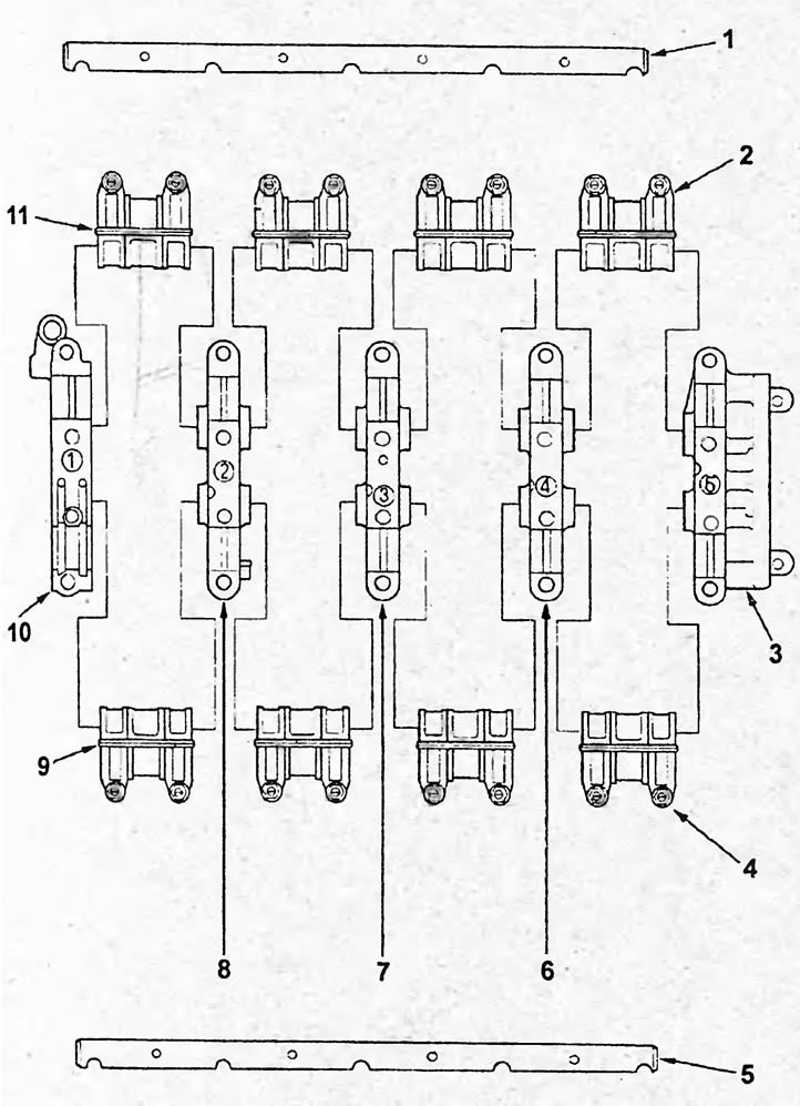
VTEC rocker arm block (type 3). 1 - exhaust valve rocker arm shaft, 2 - exhaust valve rocker arms, 3 - camshaft bearing cover No.5, 4 - intake valve rocker arms, 5 - intake valve rocker arm shaft, 6 - camshaft bearing cover No.4, 7 - camshaft bearing cover No.3, 8 - camshaft bearing cover No.2, 9, 11 - rubber, 10 - camshaft bearing cover No.1.
Tightening torque:
- stage 1 - 39 Nm
- stage 2 -90°
7. If new bolts are used, tighten the bolts an additional 90°.
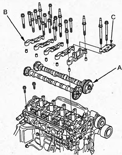
8. Install the VTEC rocker arm assembly and camshafts.
a) Clean the surface of the rocker arm holder in the area of cylinder No.5.
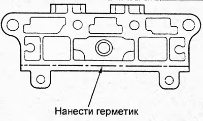
b) Apply a layer of sealant to the contact surface of the rocker arm holder as shown in the figure.
Note: The parts must be installed within the time specified in the sealant application instructions. Otherwise, the sealant must be removed and reapplied.
c) Install the bolts (A) into the VTEC rocker arm assembly and remove the VTEC rocker arm assembly (B).
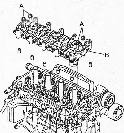
d) Remove the bolts from the rocker arm holder.
d) Install the camshafts (A) in the cylinder head bed so that the marks on the variable valve timing clutch and on the sprocket are facing upwards. Install the camshaft bearing caps (B) and the upper timing chain guide (C).
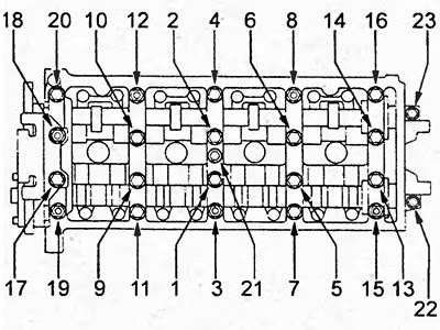
e) Tighten the camshaft bearing cap bolts in 2 passes in the sequence shown in the figure.
Tightening torque:
- bolts 1-21 — 22 Nm
- bolts 21, 22, 23 - 12 Nm
9. Install the timing chain.
10. Check the thermal clearance in the valve drive.
11. Install the cylinder head cover.
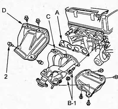
12. (Models with 1 and 2 type rocker blocks) Install a new gasket (A), exhaust manifold (C), exhaust manifold bracket (E) and tighten the mounting bolts (B), then install the exhaust manifold heat shield (D).
Tightening torque:
- bolts "1" and "2" - 44 Nm
- bolts "3" - 22 Nm
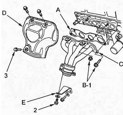
13. (Models with 3 type rocker block) Install a new gasket (A), exhaust manifold (C) and tighten the mounting bolts (B), then install the exhaust manifold heat shield (D).
Tightening torque:
- bolts "1" - 44 Nm
- bolts "2" - 22 Nm
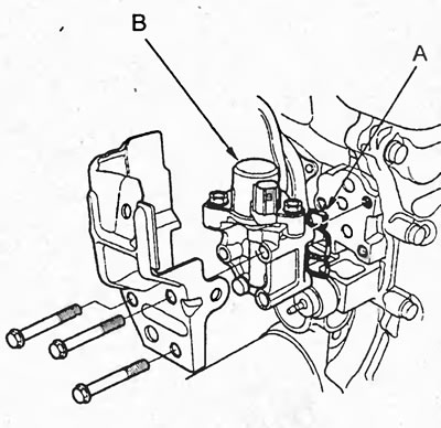
14. Install a new gasket (A) and install the valve of the variable valve timing and lift height (VTEC) system (B).
Tightening torque - 12 Nm
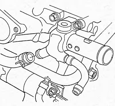
15. Install the cooling system bypass hose.
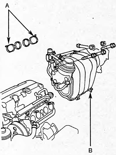
16. (Models with 1 and 2 type rocker blocks) Install the intake manifold (B) with new sealing rings (A) and tighten the mounting bolts and nuts.
Note: The intake manifold mounting nuts and bolts are tightened crosswise in several passes.
Tightening torque: 22 Nm
17. (Models with 3 type rocker block) Install a new gasket (A), install the intake manifold (B) by installing the studs (C) and tighten the mounting bolts. Connect the hose (D) to the valve of the additional air supply system to the injectors.
Note: The intake manifold mounting bolts and studs are tightened crosswise in several passes.
Tightening torque: 22 Nm
18. (Models with 1 and 2 type rocker blocks). Connect the bypass solenoid valve connector (A), hose (B) to the positive crankcase ventilation valve and tighten the solenoid valve mounting bolt (C).
Tightening torque - 12 Nm
19. (Models with 3 type rocker block). Connect the positive crankcase ventilation hose (A) and tighten the bolts (B) and (C) securing the retainer and the wire harness bracket.
Tightening torque - 12 Nm
20. Connect the cooling system bypass hoses.
21. Install the wire harness protector (A), then tighten the connecting pipe mounting bolt (B) and the vacuum booster pipe mounting bolts (C).
Tightening torque - 12 Nm
22. Connect the connectors to the sensors and valves specified in item 5 of the "Removal" subsection.
23. Connect the wire to the negative terminal of the battery.
24. Make sure all tubes and connectors are connected correctly.
25. Check for fuel leaks.
Turn the ignition key to the "ON" position (do not start the engine) so that the fuel pump runs for 2 seconds and increases the pressure in the fuel line. Repeat this operation 2-3 times and check the fuel line for fuel leaks.
26. Fill with coolant and bleed air.
Replacing crankshaft seals
1. Replace the front crankshaft oil seal.
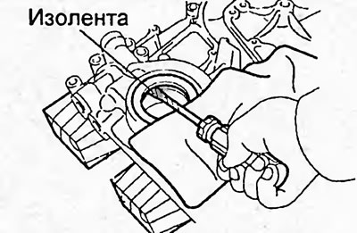
a) Using a screwdriver and hammer, knock out the oil seal as shown in the figure.
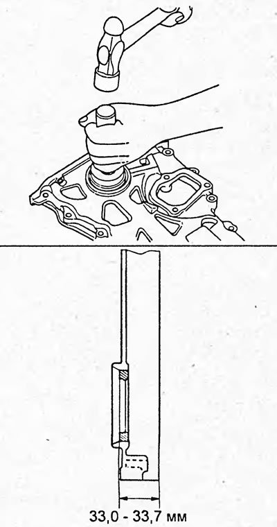
b) Using a drift or tube of suitable diameter and a hammer, press the new seal until its surface is flush with the cover.
c) Apply grease to the lip of the oil seal.
2. Replace the rear crankshaft oil seal.
a) Using a screwdriver and hammer, knock the oil seal out of the cylinder block.
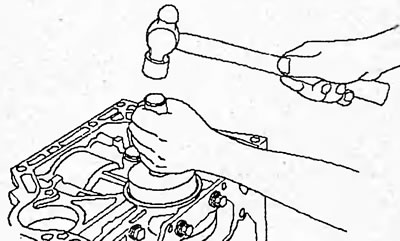
b) Using a mandrel or pipe of suitable diameter and a hammer, press the new oil seal into the cylinder block.
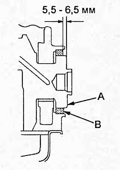
c) Make sure there is a gap between the oil seal and the crankshaft end.
Gap - 5.5-6.5 mm
(The text can be found on the website: «HONDABOOK.ru»)