
Disassembly, inspection, cleaning and repair
1. Remove the oil pan.
2. Check the axial clearance of the connecting rod bearing.
- Using a feeler gauge, measure the axial clearance of the connecting rod bearing.
Axial clearance:
- nominal - 0.15 - 0.30 mm
- maximum - 0.40 mm

D15B, D17A.
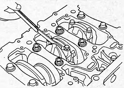
K20A.
If the axial clearance is greater than the maximum, replace the connecting rod assembly.
Replace the crankshaft if necessary.
3. Remove the connecting rod lower head cover and check the connecting rod bearing radial clearance.
a) Unscrew the two bolts securing the lower connecting rod head cover.
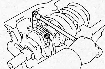
b) Check the alignment of the marks on the connecting rod and the connecting rod lower head cover to ensure its correct assembly later.
If there are no marks, use a punch to mark them on the caps and connecting rods.
c) Using a plastic-faced hammer, lightly tap the connecting rod bolts and remove the lower connecting rod cap by rocking it from side to side.
Note: The lower bearing shell must remain in the connecting rod lower end cap.
d) Clean the crankpin and bearings.
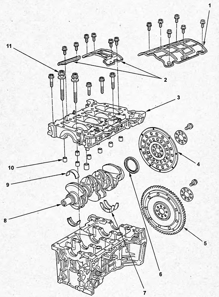
Disassembly and assembly of the cylinder block (K20A, stage 1). 1 - oil depressant (models without balance shaft block), 2 - oil depressant (models with balance shaft block), 3 - crankshaft main bearing cap, 4 - torque converter drive plate (models with automatic transmission), 5 - flywheel (models with manual transmission), 6 - rear crankshaft oil seal, 7 - thrust half rings, 8 - crankshaft, 9 - crankshaft main bearing shells, 10 - bolt guides, 11 - crankshaft main bearing cover fastening bolts.
d) Check the surfaces of the connecting rod journal and bearing for pitting and scratches.
If there are any scratches or scoring, replace the liners. If necessary, regrind the journals or replace the crankshaft.
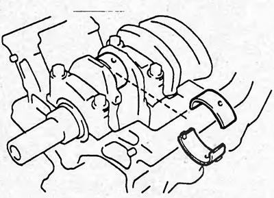
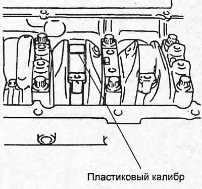
e) Install the plastic bearing clearance gauge as shown in the figure.
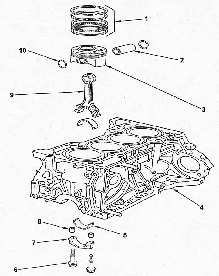
Disassembly and assembly of the cylinder block (K20A, stage 2). 1 - piston rings, 2 - piston pin, 3 - piston, 4 - cylinder block, 5 - crankshaft connecting rod bearing shell, 6 - connecting rod lower head cover fastening bolts, 7 - connecting rod lower head cover, 8 - bolt guides, 9 - connecting rod, 10 - retaining ring.
g) Install the connecting rod lower end cover, aligning the protrusions on the connecting rod lower end cover with the grooves on the connecting rod. Tighten the connecting rod lower end cover mounting bolts.
Tightening torque:
D17A, D15B — 32 Nm
K20A (models with rocker blocks of types 1 and 2):
- 1 step - 20 Nm
- step 2 - 90°
K20A (models with type 3 rocker block):
- 1 step - 29 Nm
- step 2 - 90°
c) Remove the lower connecting rod head cover.
i) Measure the width of the flattened plastic gauge at its widest point and determine the connecting rod bearing clearance.

Nominal clearance:
- D15B, D17A - 0.024 - 0.042 mm
- K20A (models with rocker blocks of types 1 and 2) — 0.021 - 0.049 mm
- K20A (models with type 3 rocker block) — 0.033 - 0.061 mm
Maximum clearance:
- D15B, D17A — 0.050 mm
- K20A (models with rocker blocks of types 1 and 2) — 0.060 mm
- K20A (models with type 3 rocker block) — 0.072 mm
If the clearance is greater than the maximum, replace the bearings. If necessary, grind or replace the crankshaft.
Selecting a connecting rod bearing shell.
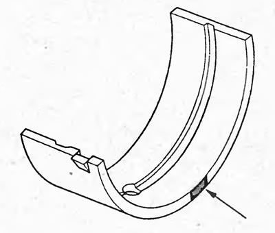
Note: There are 4 size groups of connecting rods, distinguished by marks "1", "2", "3", "4" or "|", " ||", "|||", "||||". There are also marks on the crankshaft. Select the connecting rod bearing shell depending on the marks and using the table "Choosing the connecting rod bearing shell of the crankshaft".
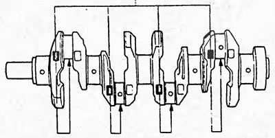

Thickness of connecting rod bearing shell.
Nominal thickness - 1.5 mm
g) Install the connecting rod lower end cover, aligning the protrusions on the connecting rod lower end cover with the grooves on the connecting rod. Tighten the connecting rod lower end cover mounting bolts.
Tightening torque:
D17A, D15B — 32 Nm
K20A (models with rocker blocks of types 1 and 2):
- 1 step - 20 Nm
- step 2 - 90°
K20A (models with type 3 rocker block):
- 1 step - 29 Nm
- step 2 - 90°
c) Remove the lower connecting rod head cover.
i) Measure the width of the flattened plastic gauge at its widest point and determine the connecting rod bearing clearance.
Nominal clearance:
- D15B, D17A - 0.024 - 0.042 mm
- K20A (models with rocker blocks of types 1 and 2) — 0.021-0.049 mm
- K20A (models with type 3 rocker block) — 0.033-0.061 mm
Maximum clearance:
- D15B, D17A — 0.050 mm
- K20A (models with rocker blocks of types 1 and 2) — 0.060 mm
- K20A (models with type 3 rocker block) — 0.072 mm
If the clearance is greater than the maximum, replace the bearings. If necessary, grind or replace the crankshaft.
Selecting a connecting rod bearing shell.
Note: There are 4 size groups of connecting rods, distinguished by marks "1", "2", "3", "4" or "|", " ||", "|||", "||||". There are also marks on the crankshaft. Select the connecting rod bearing shell depending on the marks and using the table "Choosing the connecting rod bearing shell of the crankshaft".
Table. Main Bearing Shell Thickness Deviation (D15B, D17A).
| Label | Color | Deviation, mm |
| G | Red | -0,005 - -0,008 |
| F | Pink | -0,002 - -0,005 |
| E | Yellow | -0,001 - -0,002 |
| D | Green | -0,004 - -0,001 |
| C | Brown | -0,007 - -0,004 |
| B | Black | -0,010--0,007 |
| A | Blue | -0,013--0,010 |
Table. Deviation of connecting rod bearing shell thickness (K20A models with 1 and 2 type of rocker arm block of the X/TEC system).
| Label | Color | Deviation, mm |
| G | Red | -0,008 - -0,005 |
| F | Pink | -0,005 - -0,002 |
| E | Yellow | -0,002 - -0,001 |
| D | Green | -0,001 - -0,004 |
| C | Brown | -0,004 - -0,007 |
| B | Black | -0,007 - -0,010 |
| A | Blue | -0,010 - -0,013 |
Table. Deviation of connecting rod bearing shell thickness (K20A models with 3 type of rocker arm block of the UTES system).
| Label | Color | Deviation, mm |
| G | Red | -0,014 - -0,011 |
| F | Pink | -0,011 - -0,008 |
| E | Yellow | -0,008 - -0,005 |
| D | Green | -0,005 - -0,002 |
| C | Brown | -0,002 - -0,001 |
| B | Black | -0,001 - -0,004 |
| A | Blue | -0,004 - -0,007 |
k) Remove any remaining plastic gauge from the working surfaces of the neck and liner.
4. Remove the piston and connecting rod assembly.
a) Remove carbon deposits from the top of the cylinder.
b) Remove the piston assembly with the connecting rod and upper bearing shell through the top of the cylinder block.
Note: Store pistons with connecting rods, liners and caps in sets to avoid confusion during installation.
5. Use an indicator to measure the axial clearance of the crankshaft, moving the latter "back and forth" with a screwdriver.

D15B, D17A.
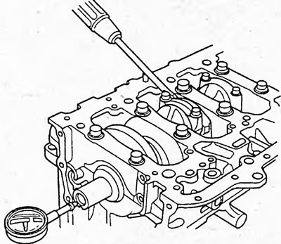
K20A.
Axial clearance:
- nominal - 0.10-0.30 mm
- maximum - 0.40 mm
If the axial clearance is greater than the maximum, replace the thrust washers and/or the crankshaft.
6. Remove the main bearing caps and check the radial oil clearances,
a) (K20A) Remove the oil catcher plates.
Tightening torque - 12 Nm
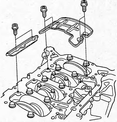
Table. Selection of main bearing shell (D15B, D17A).
| Markings on the cylinder block | A | IN | WITH | D | |
| Marks on the crankshaft | - | - | - | - | |
| 1 | Red | Pink | Yellow | Green | |
| 2 | Pink | Yellow | Green | Brown | |
| 3 | Yellow | Green | Brown | Black | |
| 4 | Green | Brown | Black | Blue | |
Table. Selection of main bearing shell (K20A).
| Markings on the cylinder block | A | IN | WITH | D | |
| Marks on the crankshaft | - | - | - | - | |
| 1 | Pink | Pink/Yellow | Yellow | Green | |
| 2 | Pink/Yellow | Yellow | Green | Green/Brown | |
| 3 | Yellow | Green | Green/Brown | Brown | |
| 4 | Green | Green/Brown | Brown | Black | |
| 5 | Green/Brown | Brown | Black | Black/Blue | |
| 6 | Brown | Black | Black/Blue | Blue | |

Disassembly and assembly of the cylinder block (D15B, D17A). 1 - piston rings, 2 - piston, 3 - piston pin, 4 - cylinder block, 5 - connecting rod lower head cover, 6 - crankshaft connecting rod bearing shell, 7 - connecting rod.
Table. Selection of connecting rod bearing shell.
| Markings on the cylinder block | 1 or | | 2 or || | 3 or ||| | 4 or |||| | |
| Marks on the crankshaft | - | - | - | - | |
| A | Red | Pink | Yellow | Green | |
| IN | Pink | Yellow | Green | Brown | |
| WITH | Yellow | Green | Brown | Black | |
| D | Green | Brown | Black | Blue | |
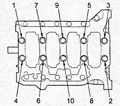
b) (K20A) Unscrew the bolts (8 mm) in the sequence shown in the figure.

c) Check the alignment of the marks on the main bearing caps and the cylinder block to ensure correct assembly later. If there are no marks, use a punch to mark them on the caps and the cylinder block.
d) Uniformly loosen and unscrew the main bearing cap mounting bolts in several passes in the sequence shown in the figure.
d) Using a screwdriver, separate and remove the main bearing caps.

D15B,D17A.
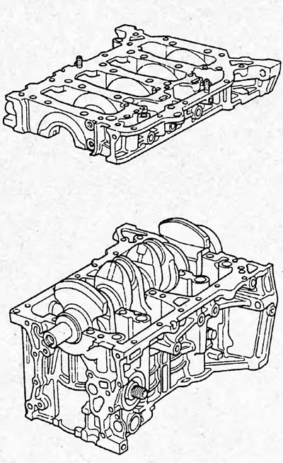
K20A.
Note:
- Remove the main bearing cap by slowly rocking it from side to side to avoid damaging the mating surfaces of the bearing cap and cylinder block.
- Keep the main bearing caps together with the lower bearing shells to avoid mixing them up during installation.
e) Raise the crankshaft.
Note: Leave the upper bearing shells and upper thrust washers in the cylinder block.
g) Clean each main journal and bearings.
h) Check the surface of each main journal and bearing for pitting and scratches.
If the journal or bearing is damaged, replace the bearings. If necessary, regrind or replace the crankshaft.
i) Install the upper crankshaft main bearing shells and place the crankshaft in the cylinder block.
k) Place a plastic bearing clearance gauge on each main journal.
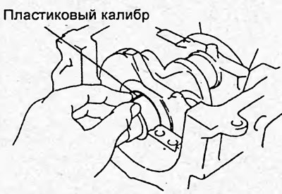
l) Install the main bearing caps.
m) Apply a layer of engine oil to the threads and under the heads of the main bearing cap bolts.
n) Tighten the crankshaft main bearing cap bolts in the sequence shown in the figure.
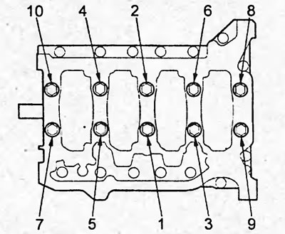
Tightening torque:
- D17A — 51 Nm
- D15B — 45 Nm
K20A:
- 1 step - 29 Nm
- step 2 - 56°
o) Loosen the crankshaft main bearing cap bolts and remove the caps.
p) Measure the maximum width of the flattened plastic gauge, using it to determine the value of the radial oil clearance.
Nominal clearance:
D17A:
- necks No.1, 5 — 0.018 - 0.036 mm
- neck No.2, 3.4 — 0.024 - 0.042 mm
D15B:
- necks No.1, 5 — 0.018 - 0.036 mm
- neck No.2, 3.4 — 0.020 - 0.038 mm
K20A:
- necks No.1, 2, 4, 5 — 0.017 - 0.041 mm
- neck #3 — 0.025 - 0.049 mm
Maximum clearance:
- D15B, D17A — 0.05 mm
- K20A - 0.055 mm

If the oil clearance is greater than the maximum, replace the bearings. If necessary, regrind or replace the crankshaft.
p) Selection of bearing shells for crankshaft main journals.
- To select the bearing, use the marks on the cylinder block (at the rear of the cylinder block) and on the crankshaft, as shown in the figures.
Note: to select the main bearing shell, see the table "Selection of the main bearing shell", where from left to right the bearing sizes go in the decreasing direction and from top to bottom the bearing sizes go in the decreasing direction.
Note: If the marks are not visible due to dirt, use only solvent or detergent to clean, do not use a scraper.
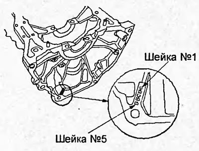
D15B, D17A.

K20A.

Decoding marks on the cylinder block.
Nominal bed diameter - 59 mm
Table. Marks on the cylinder block (K20A).
| Label | Deviation, mm |
| 1 or A | 0,000 - 0,006 |
| 2 or B | 0,006-0,012 |
| 3 or C | 0,012-0,018 |
| 4 or D | 0,018-0,024 |
Table. Marks on the cylinder block (D15B, D17A journals No.1 and No.5).
| Label | Deviation, mm |
| A | -0,006 - 0,000 |
| IN | 0,000 - 0,006 |
| C | 0,006-0,012 |
| D | 0,012-0,018 |
Table. Marks on the cylinder block (D15B, D17A journals No.2, No.3 and No.4).
| Label | Deviation, mm |
| A | 0,000 - 0,006 |
| IN | 0,006-0,012 |
| WITH | 0,012-0,018 |
| D | 0,018-0,024 |
Main bearing shell thickness.
Nominal thickness - 2 mm
Table. Main Bearing Shell Thickness Deviation (D15B, D17A).
| Label | Color | Deviation, mm |
| G | Red | -0,002 - -0,005 |
| F | Pink | 0,001 - -0,002 |
| E | Yellow | 0,004 - 0,001 |
| D | Green | 0,007 - 0,004 |
| WITH | Brown | 0,010-0,007 |
| IN | Black | 0,013-0,010 |
| A | Blue | 0,016-0,013 |
Table. Main Bearing Shell Thickness Deviation (K20A models with 1 and 2 type of rocker arm block VTEC system).
| Label | Color | Deviation, mm |
| F | Pink | -0,006 - -0,003 |
| E | Yellow | -0,003 - 0,000 |
| D | Green | 0,000 - 0,003 |
| WITH | Brown | 0,003 - 0,006 |
| IN | Black | 0,006 - 0,009 |
| A | Blue | 0,009 - 0,012 |
Table. Main Bearing Shell Thickness Deviation (K20A models with type 3 rocker arm block VTEC system).
| Label | Color | Deviation, mm |
| F | Pink | -0,003 - 0,000 |
| E | Yellow | 0,000 - 0,003 |
| D | Green | 0,003 - 0,006 |
| WITH | Brown | 0,006 - 0,009 |
| IN | Black | 0,009 - 0,012 |
| A | Blue | 0,012 - 0,015 |
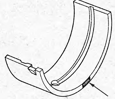
7. Check the connecting rod lower cover mounting bolts.
a) Using a micrometer, measure the thread diameter of the bolts at locations (A) and (B) indicated in the figure.

b) Subtract the diameter value (A) from the diameter value (B) and find the difference.
Difference - 0-0.1 mm
If the difference in diameters is greater than the specified value, replace the bolt.
8. Clean the cylinder block.
a) Remove any remaining gaskets from the working surfaces of the cylinder block.
b) Using solvent and a soft brush, thoroughly clean the cylinder block.
9. Check the cylinder block gas joint surface for flatness using a precision ruler and a flat feeler gauge.
- Nominal flatness - 0.07 mm
- Maximum flatness - 0.10 mm

If the flatness exceeds the specified value, replace the cylinder block.
10. Check the cylinder bore for vertical scratches.
If there are deep scratches, replace the cylinder block.
11. Measure the cylinder diameter.
Using a bore gauge, measure the cylinder diameter at three levels "A", "B" and "C" in the transverse (X-X) and longitudinal (YY) directions, as shown in the figure.
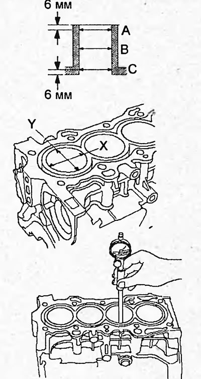
Nominal cylinder diameter:
D15B, D17A:
- Nominal size - 75.00 - 75.02 mm
- 1st repair size (0.25) - 75.25 - 75.27 mm
- 2nd repair size (0.50) — 75.50 - 75.52 mm
- Minimum size - 75.07 mm
K20A:
Nominal size:
- 1 type - 86.01 - 86.02 mm
- 2 type - 86.00 - 86.01 mm
- 1st repair size (0.25) — 86.25 - 86.26 mm
- Minimum size - 86.07 mm
The maximum difference between measurements is 0.05 mm
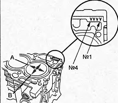
K20A.
If the diameter is greater than the maximum allowable, bore all cylinders or replace the cylinder block.
[The text of the article is available on the website HONDABOOK.ru]