
Checking the motor circuit
Attention! Before starting the test, study the relevant electrical diagrams (see Wiring diagrams - general information). Checking the presence of voltage at the connector terminals is carried out by testing them with a probe of a grounded probe lamp. Turning on the lamp confirms the presence of voltage at the terminal. If it is not possible to identify the cause of the malfunction during the checks described below, the car should be driven to a workshop for a more complete diagnosis of the system.
If the windshield wipers are running too slowly, check the battery level first (see chapter Current service). With a good battery, remove the wiper motor (see below) and try to move the brushes by hand, checking the freedom of their movement. If necessary, make the appropriate repair of the rods and lubricate the axle units. Install the electric motor in place, turn on the ignition and restart the brushes. If the speed of the wipers after the corrections made has not returned to normal, check the quality of the contact connections of the circuit and the reliability of fixing the connectors, paying special attention to the condition of the ground. If the circuit is good, replace the electric motor.
If the wipers fail to activate, check the condition of the appropriate fuse. If the fuse is OK, install a jumper wire between the drive motor ground terminal and chassis ground. Repeat check. If the wipers now start to function normally, restore the reliability of the ground contact nodes. If the motor still does not run, set the brush control switch to maximum speed (HI) and check the presence of voltage at the connector of the wiring connected to the electric motor. With proper power supply. If there is voltage, test the motor by connecting directly to the battery using a fused jumper wire (see illustration below).
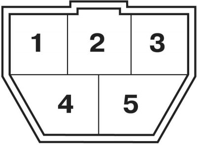
If the motor is now running, check the condition of the wiper linkages. If the motor does not start, replace it. If there is no voltage, check the power supply to the built-in control unit. If there is voltage on the built-in control unit and its absence on the motor, check the correct operation of the switch (see Check of serviceability of functioning and replacement of understeering switches). If the switch is in order, the built-in control unit is most likely out of order.
If the intermittent wiper operation fails, check the condition of the circuit in the area between the switch and the integrated control unit. If the wiring is in order, you should diagnose the built-in control unit in a car service.
If the brushes stop in the position they occupy when the switch is turned to the OFF position, check the power supply to the motor limit switch. Voltage should be present on the corresponding motor connector wire with the switch turned OFF and the (ON) ignition.
If the brushes stop only after the ignition is turned off, disconnect the wiring from the wiper control switch. If the brushes stop now, replace the switch. If the brushes continue to function, therefore the limit switch of the electric motor is damaged, replace the motor.
If the brushes do not go under the line of the hood when stopped, check the drive rod for foreign objects under it. If nothing prevents the brushes from leaving the park position, check the wiring in the section of the circuit between the switch and the motor. If there are no breaks, replace the motor.
Electric motor replacement
Front wipers
1. Remove the lever (leash) windscreen cleaner.
2. Remove the front fairing cover (see chapter Body).
3. Disconnect the drive motor connector.
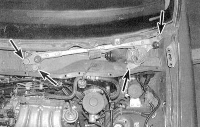
4. Remove the wiper drive assembly from the lower fairing cover (see accompanying illustration).
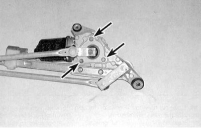
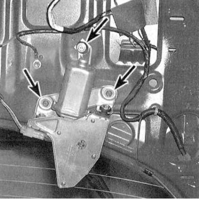
5. Turn out bolts of fastening of the motor to driving assembly (see accompanying illustration).
6. Remove the motor.
7. Installation is carried out in the reverse order.
Rear wiper
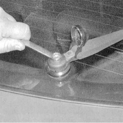
1. Remove a decorative cover of the lever of a back screen wiper for the purpose of providing access to a fixing nut. Loosen the nut and remove the lever from the spindle (see accompanying illustration).
2. Open the tailgate and remove the interior upholstery panel (see chapter Body).
3. Disconnect the drive motor connector.
4. Give bolts of a fixing arm and remove the motor (see accompanying illustration).
5. Installation is carried out in the reverse order.