
Attention! The vehicles covered in this manual are equipped with airbags (SRS). When performing any work near the shock sensors, steering column or instrument panel, turn off the SRS (see Airbags - general information). Do not test SRS models with any type of diagnostic equipment.
Combined steering column switches for lighting and windshield wipers/washers
Examination
1. The ambient light combination switch is located on the left side of the column and controls the direction indicators, headlights, signal light and parking lights. On the opposite side of the column there is a switch for controlling the wipers/windshield washers.
2. Remove the switch (And) (see paragraph 1, Replacement).
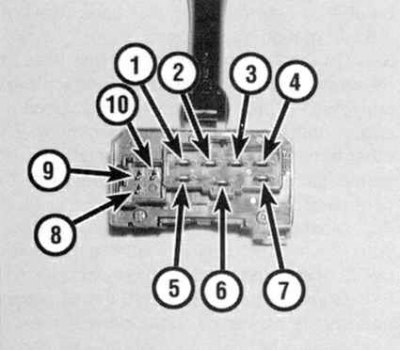
3a. Using an ohmmeter or a probe lamp equipped with an individual power source, check the correct presence of conductivity between the switch terminals in its various positions (see accompanying illustrations and tables below): Identification card for the terminals of the combined lighting control stalk
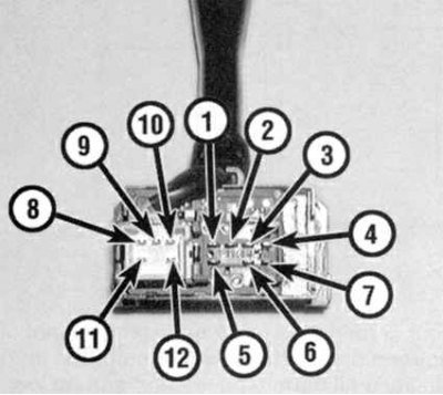
3b. Identification card for the terminals of the combined windshield wiper / washer control stalk. In case of detection of violations, replace the switch.
Status map of the lighting control stalk switch
| Switch position | Conductivity between terminals |
parking lights | 1 and 2 |
| Headlights (dipped beam) | |
Civic (USA) | 1 and 2; 3 and 6 |
Civic (Canada) | 1 and 2; 3, 4 and 6 |
Integra | 1 and 2; 4 and 6 |
| Headlights (high beam) | |
Civic (USA) | 1 and 2; 5 and 6 |
Civic (Canada) | 1 and 2; 4, 5 and 6 |
Integra | 1 and 2; 4, 5 and 6 |
Flashing headlights | 5 and 6 |
Right turn indicators | 8 and 10 |
Left turn indicators | 8 and 9 |
Status map of the stalk switch for controlling the windshield and rear window wipers / washers
| Switch position | Conductivity between terminals |
Windshield Wiper/Washer Control Switch | |
Off | 1 and 7 |
Interval mode | 1 and 7; 3 and 4 |
Slow mode | 1 and 5 |
Quick mode | 2 and 5 |
glass washing | 4 and 8 |
Fog | 2 and 5 |
| Rear wiper/washer control switch | |
Off | 1 and 2 |
On | 1 and 3 |
glass washing | 4 and 6 |
Replacement
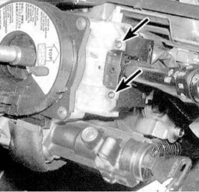
1a. Remove sections of a casing of a steering column. Using a small screwdriver, carefully disconnect the switch electrical connector. Remove the two fixing screws.
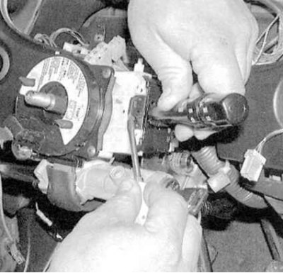
1b. Remove the switch assembly from the steering column (see accompanying illustrations).
2. Installation is carried out in the reverse order.
Speed control operation control switch (tempostat)
Examination
1. Remove the switch from the steering column (see paragraph 3 below).
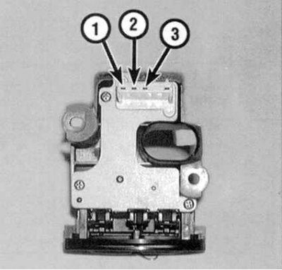
2. Using an ohmmeter or a probe lamp equipped with an individual power source, check for continuity between the switch terminals in both of its positions (see accompanying illustration). Replace assembly if necessary.
Replacement
1. Disconnect the negative cable from the battery and wait at least three minutes before proceeding with the procedure.
Attention! If the stereo system installed in the car is equipped with a security code, before disconnecting the battery, make sure that you have the correct combination to activate the audio system!
2. Remove the cover from the switch.
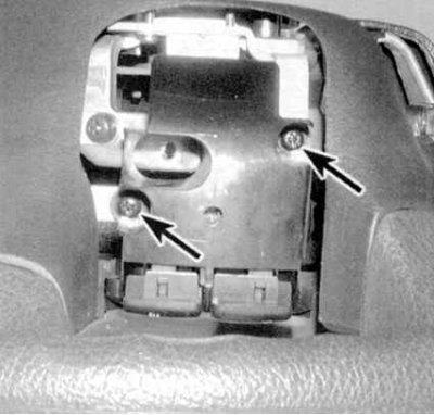
3. Remove the fixing screws (see accompanying illustration), disconnect the electrical connectors and remove the switch from the steering wheel.
3. Installation is carried out in the reverse order.