
The window lifts can be controlled from the driver's seat using the main switch or by manipulating individual door switches. Each window is equipped with an individual reversible drive electric motor. By switching the switch key, the polarity of the motor connection changes and, as a result, the direction of its rotation.
The circuit is protected by a fuse and a circuit breaker. Each of the electric motors is additionally equipped with an individual circuit breaker, preventing the possibility of the entire system being disabled if a single glass gets jammed.
The electric window lifter operates only when the ignition is on. Additionally, many models have the ability to lock the rear window lifters (and sometimes the front passenger) doors from the main switch. Do not forget about this function when checking for windshield wiper failures.
The procedures described are of a very general nature, so if their implementation does not allow you to clearly identify the cause of the failure, take the car to a service station for more detailed diagnostics.
- If the window lifts fail, always check the fuse and circuit breaker first.
- If the rear door windows are controlled only by the main switch, check the continuity of the interlock switch in the released state. Replace the faulty switch.
- Check the condition of the wiring in the circuit section between the switches and the fuse box. Make any necessary repairs.
- If the main switch of only one of the windows fails to operate, check the correct operation of this window lifter from the other switch.
Note: The latter does not apply to the driver's door window.
- If the same window regulator operates properly from a different switch, check the continuity of the switch.
- If the switch is OK, check for opens and shorts in the circuit between the suspect switch and the power window motor for that particular window.
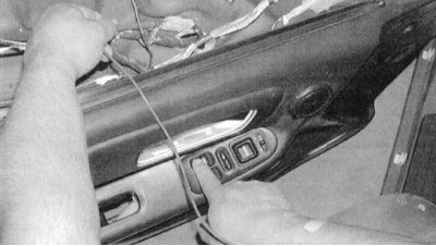
- If the window does not operate from both switches, remove the interior trim panel from the door in question and check for voltage at both the switch and the drive motor (with the corresponding switch position) (see accompanying illustration).
Door Power Window Master Control Switch State Map (Civic Coupe/Hatchback)
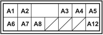
| Switch position | Presence of conductivity between the terminals |
| Left front (driver's) door | The driver's switch cannot be tested |
| Right front door | |
| oFF. | A2, A5 and A7 |
| uP | A2 and A5; A6 and A7 |
| dOWN | A2 and A6; A5 and A7 |
| The check is carried out with the main locking switch on | |
Door Power Window Master Control Switch State Map (Civic Sedan)
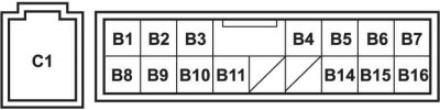
| Switch position | Presence of conductivity between the terminals |
| Left front (driver's) door | The driver's switch cannot be tested |
| Right front door | |
| oFF. | B1, B11 and C1 |
| uP | B1 and B2; B11 and C1 |
| dOWN | B2 and B11; B1 and C1 |
| Left rear door | |
| oFF. | B14, B16 and C1 |
| uP | B14 and B15; B16 and C1 |
| dOWN | B15 and B16; B14 and C1 |
| Right rear door | |
| oFF. | B9, B10 and C1 |
| uP | B8 and B9; B10 and C1 |
| dOWN | B8 and B10; B9 and C1 |
| The check is carried out with the main locking switch on | |
Passenger Door Power Window Control Switch State Map (Civic, including rear door switches on Sedan models)
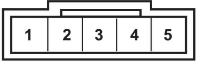
| Switch position | Presence of conductivity between the terminals |
| ON. | 2 and 3; 4 and 5 |
| UP | 1 and 4; 2 and 3 |
| DOWN | 1 and 3; 4 and 5 |
Door Power Window Master Control Switch State Map (Integra Hatchback)
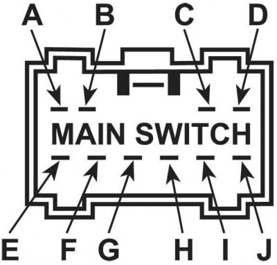
| Switch position | Presence of conductivity between the terminals |
| Left front (driver's) door | The driver's switch cannot be tested |
| Right front door | |
| oFF. | D, H and I |
| uP | D and H; I and J |
| dOWN | D and I; H and J |
| The check is carried out with the main locking switch on | |
Door Power Window Master Control Switch State Map (Integra Sedan)
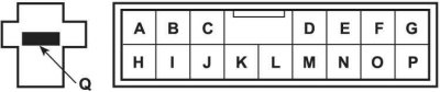
| Switch position | Presence of conductivity between the terminals |
| Left front (driver's) door | The driver's switch cannot be tested |
| Right front door | |
| oFF. | I, J and Q |
| uP | H and J; I and Q |
| dOWN | H and I; J and Q |
| Left rear door | |
| oFF. | F, G and Q |
| uP | E and G; F and Q |
| dOWN | E and F; G and Q |
| Right rear door | |
| oFF. | O, P and Q |
| uP | N and P; O and Q |
| dOWN | N and O; P and Q |
| The check is carried out with the main locking switch on | |
Rear Door Window Control Switch State Map (Integra Sedan)
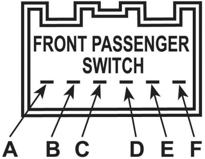
| Switch position | Presence of conductivity between the terminals |
| ON. | A and B; C and E |
| UP | A and B; D and E |
| DOWN | B and D; C and E |
Front Passenger Door Power Window Control Switch State Map (Integra Hatchback and Sedan)
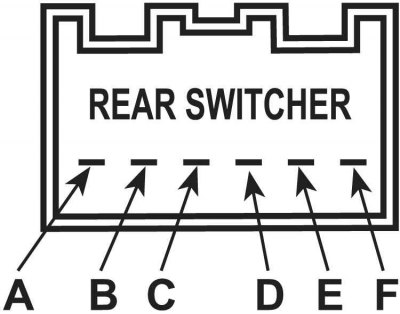
| Switch position | Presence of conductivity between the terminals |
| ON. | A and B; D and E |
| UP | B and C; D and E |
| DOWN | A and B; C and D |
- To assess the condition of the switch, check it according to the instructions provided.
- With the power supply to the electric motor working properly, separate the glass from the window regulator (see Chapter Body). Move the glass up and down, checking its freedom of movement. Also check the condition of the regulator. If the regulator is normal and the glass moves freely in both directions, replace the drive electric motor. If the smooth movement of the components is disrupted, eliminate the detected interference, lubricate the rubbing units and replace the damaged parts.
Note: The drive motor is integrated into the window regulator assembly, the removal procedure for which is described in Chapter Body.
- If there is no power to the motor, check the wiring between the switches and the motors for continuity (if necessary, refer to the electrical connection diagrams at the end of this Chapter). If the circuit is equipped with an actuator relay, check the serviceability of the power supply and grounding of the latter.
- After making the necessary corrections, re-test the operation of the window lifts.