
HondaBook.ru
Auto companies Volkswagen Auto companies Ford Auto companies Lada Auto companies Skoda Auto companies BMW Auto companies Mazda Auto companies Peugeot
English Русский
Български
Беларускі
Український
Српски
Hrvatski
Română
Polski
Slovenský
Magyar
Bookmark Contacts Sitemap   


Accord Civic Fit / Jazz CR-V HR-V Others Articles
Civic 3 and 4 (1983-1991) Civic 5 and 6 (1991-2000) Civic 6 (1995-2000) Civic 7 (2000-2005) Civic 8 (2005-2011)

Checking and repairing the rear window defroster (Honda Civic 6)

  • Main
  • Honda Civic
  • 6 (1995-2000)
  • Electrical equipment
  • Equipment and devices
  • Checking and repairing the rear window defroster
0
Contents: Examination ⇊ Restorative repair ⇊
The working element of the rear window heater is a horizontal grid of conductive threads glued to the inner surface of the glass. Power is supplied to the heater through a 30 A fuse from the power distribution unit located in the engine compartment of the car. The heater is turned on using a switch located on the instrument panel of the car. On Integra models, the continuous operation time of the heater is limited by a timer included in the built-in control unit.

Minor breaks in the conductive threads of the working element grille can be repaired without dismantling the rear window.

Examination


1. Turn on the ignition and rear window defroster.

2. Press the positive probe of the voltmeter to the positive terminal of the heating element grid, press the negative probe to the negative terminal. The device should register battery voltage, otherwise check the condition of the fuse, switch and connecting wiring. If the voltage is normal, but part of the heater does not work. Proceed to the next step of testing.
2. Press the positive probe of the voltmeter to…


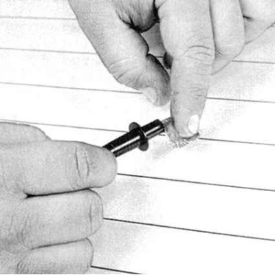
3. In order to measure the voltage during the tests described below, wrap the positive probe of the voltmeter with metal foil, which can then be easily pressed with your finger directly to the conductive thread of the heating element grid (see accompanying illustration). Connect the negative probe of the meter to the negative terminal of the grid.


3. In order to measure the voltage during the…


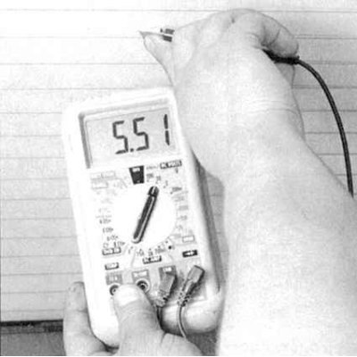
4. Measure the voltage in the center of each of the grid threads (see accompanying illustration).

5. A reading of 5-6 V indicates that the filament is in good condition. A zero reading indicates a break between the center of the filament and the positive side of the element. A reading that is twice as high (10-12 V) indicates a break between the center of the filament and the negative side of the element. Check each of the grid filaments in turn.

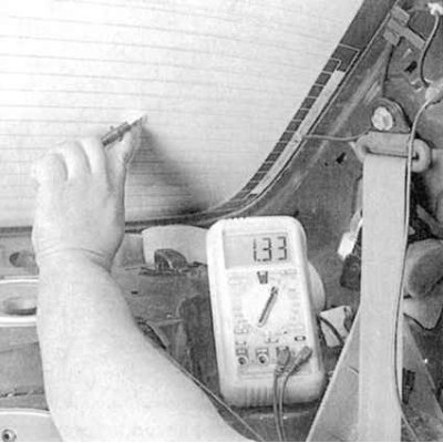
6. If there are no breaks, connect the negative probe to the chassis ground and repeat the check - the readings should not change, otherwise there is a violation of the quality of the grid grounding.
6. If there are no breaks, connect the negative…


7. To locate the break, press the negative probe of the voltmeter to the negative terminal of the heating element grid. Using the positive probe wrapped in foil, begin to probe the conductive filaments of the grid, moving from the power supply side to the ground. At the break point, the reading of the device should drop from several volts to zero (see accompanying illustration).


Restorative repair


1. Restoration of the integrity of conductive threads is carried out using a special repair kit such as Dupont No.4817. The basis of the kit is conductive epoxy paste, supplied complete with a hardener.

2. Before starting any repair work on the working element grille, turn off the heater and allow the element to cool for a few minutes.

3. Lightly clean the damaged area of the thread with felt, then wipe it thoroughly with alcohol.

4. Apply two strips of tape along the area of the thread to be repaired.

5. Thoroughly mix the epoxy paste with the hardener.
5. Thoroughly mix the epoxy paste with the…


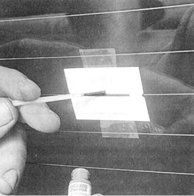
6. Apply the resulting composition to the damaged area (with an overlap of approximately 20 mm on the edges of the undamaged thread) (see accompanying illustration).

7. The final polymerization of the compound occurs after 24 hours, after which the protective tape strips can be removed from the glass.
This article is available at: russian, bulgarian, belarusian, ukrainian, serbian, croatian, romanian, polish, slovak, hungarian
This information has been verified: Timofey Goryachev
Share with friends:
◀ Previous
Civic 6: Equipment and devices
Next ▶

Checking the serviceability and replacing the horn
Checking and replacing the windshield wiper drive electric motor
Daytime running lights (DRL)
Replacing lamps
Headlight replacement
Speed control system (tempostat) — general information and testing
Electric window lifters — general information and testing
Single lock — general information and serviceability check
Electric drive of outside rear view mirrors — general information and testing
Airbags — General Information
See also other articles from Honda manuals:
Checking and repairing the rear window defroster Honda Accord 6 (1997-2002)
Rear window defroster Honda Fit 1 (2001-2008)
Checking the rear wheel alignment Honda CR-V 2 (2002-2006, petrol)
Rear window defroster Honda HR-V 1 (1998-2006, petrol)
Rear Window Defogger — Checking the Noise Suppressing Condenser Honda Avancier 1 (1999-2003, petrol)
Link in different formats to this article
Comments and feedback from visitors
No comments yet


How much will 47 + 46 ?


Civic 8 (2005-2011) 
  • General information
  • Technical data
  • Governing bodies
  • Driving and maintenance
  • Power unit
  • Gasoline engines (L13A)
  • Gasoline engines (R18A)
  • Diesel engines (N22A)
  • Cooling and lubrication (L13A)
  • Cooling and lubrication (R18A)
  • Cooling and lubrication (N22A)
  • Injection system (gasoline)
  • Injection system (diesel)
  • Toxicity reduction system
  • Troubleshooting
  • Transmission
  • Clutch and drive shafts
  • Mechanical gearbox
  • Chassis and running gear
  • Suspension and wheels
  • Steering
  • Brake system
  • Body and interior
  • Exterior (external elements)
  • Doors, locks and windows
  • Electrical equipment
  • Equipment and devices
  • Headlights and lighting
  • Power devices
  • Electrical circuits
Civic 7 (2000-2005) 
  • General information
  • User manual
  • Maintenance
  • Power unit
  • Engines D15B and D17A
  • K20A Engines
  • Overhaul engine
  • Cooling system
  • Lubrication system
  • Fuel injection system
  • Toxicity reduction system
  • Engine electrical equipment
  • Transmission
  • Clutch
  • Manual gearbox
  • Automatic gearbox
  • Variator (CVT)
  • Drive shafts
  • Chassis and running gear
  • Car suspension
  • Steering
  • Brake system
  • Body and interior
  • Exterior (external elements)
  • Interior (internal elements)
  • Doors, locks and windows
  • Heater and air conditioner
  • Manual air conditioner
  • Automatic air conditioner
  • Security system
  • Electrical equipment
  • Equipment and devices
  • Headlights and lighting
  • Windscreen wipers
  • Audio system
  • Electrical diagrams
Civic 6 (1995-2000) 
  • General information
  • Introduction to guide
  • User manual
  • Maintenance
  • Power unit
  • Engine in car (Civic)
  • Engine in car (Integra)
  • Engine overhaul
  • Cooling and heating
  • Power and exhaust systems
  • Engine electrical equipment
  • Engine management systems
  • Transmission
  • Manual gearbox
  • Automatic transmission (AT/CVT)
  • Clutch and drive shafts
  • Chassis and running gear
  • Brake system
  • Car suspension
  • Steering
  • Body and interior
  • Exterior (external elements)
  • Interior (internal elements)
  • Doors, locks and windows
  • Electrical equipment
  • Equipment and devices
  • Electrical circuits
Civic 5 and 6 (1991-2000) 
  • Power unit
  • SOHC engines
  • DOHC engines
  • Engine overhaul
  • Cooling and lubrication system
  • Intake and exhaust system
  • Fuel injection system (SOHC)
  • Fuel injection system (DOHC)
  • Carburetor
  • Transmission
  • Clutch
  • Manual gearbox S4C
  • Manual gearbox S40
  • Automatic gearbox
  • Drive shafts
  • Chassis and running gear
  • Car suspension
  • Steering
  • Brake system
  • Body and interior
  • Body elements
  • Heater and air conditioner
  • Electrical equipment
  • Power devices
  • Equipment and instruments
  • Electrical circuits
Civic 3 and 4 (1983-1991) 
  • General information
  • Maintenance
  • Power unit
  • Engine in a car
  • Engine overhaul
  • Cooling system
  • Power and exhaust system
  • Engine electrical equipment
  • Emission control system
  • Transmission
  • Mechanical gearbox
  • Automatic gearbox
  • Clutch and drive shafts
  • Four-wheel drive
  • Chassis and running gear
  • Brake system
  • Car suspension
  • Steering
  • Body and interior
  • Body elements
  • Electrical equipment
  • Equipment and devices
  • Electrical circuits
HondaBook.ru © 2018–2026 • Mobile version • Sitemap: EN BG BY UA RS HR RO PL SK HU • Feedback • Driver Information • Search system • Bookmark
Accord 3 (1985-1989) • Accord 6 (1997-2002) • Civic 3 and 4 (1983-1991) • Civic 5 and 6 (1991-2000) • Civic 6 (1995-2000) • Civic 7 (2000-2005) • Civic 8 (2005-2011) • Fit 1 (2001-2008) • CR-V 1 (1995-2001) • CR-V 2 (2002-2006) • HR-V 1 (1998-2006) • Avancier 1 (1999-2003) •
 
This website uses cookies to ensure proper functioning. By clicking "OK," you agree.