
Contents: Torque converter, transmissions and…⇊ Hydraulic control ⇊ Locking mechanism ⇊ Gear selection ⇊ Couplings ⇊ Power flow ⇊
There are two types of automatic transmissions, the 7-position automatic transmission is a combination of a 3-element torque converter and a 3-shaft automatic transmission that provides 4 forward speeds and reverse. The 6-position transmission is a 3-element torque converter and a 2-shaft transmission that provides 4 speeds and reverse. The single unit is located in line with the engine.
Torque converter, transmissions and clutches.
The torque converter consists of a pump, turbine, and reactor, all combined into one unit. The torque converter is connected to the engine crankshaft so that they rotate together as one unit when the engine is turning. Near the outside of the torque converter is a ring gear that engages the starter when the engine is starting. The entire torque converter unit acts as a flywheel, transmitting power to the transmission input shaft.
the 7-position transmission has 3 parallel shafts: primary, secondary and auxiliary shaft. The 6-position transmission has two parallel shafts: primary and secondary. The primary shaft is located in line with the engine crankshaft. The primary shaft includes the 1st, 2nd/4th clutches and gears for 3rd, 2nd, 4th, reverse gear pinion and 1st (the 3rd gear is integral with the primary shaft, while the reverse gear is integral with the 4th gear). The secondary shaft includes the 3rd clutch and gears for 3rd, 2nd, 4th, reverse, 1st and parking. The reverse gear pinion and 4th gear can be connected to the center of the secondary shaft, providing 4th or reverse gear, depending on the selector movement. The auxiliary shaft includes the 1st locking clutch and gears for 1st and 4th.
The gears on the input shaft are in constant mesh with the gears on the output shaft. When a certain combination of gears in the transmission are in mesh with the clutches, power is transferred from the input shaft to the output shaft to provide positions [D4], [D3], [2], [1], and [R].
Hydraulic control
Automatic transmission S4PA
The valve assembly includes a main level housing, a regulator valve housing and a control valve housing separated by the corresponding separating plates. They are fixed to the torque converter housing. The main level housing consists of a manual control valve, a 1-2 switching valve, a 2-3 switching valve, a 3-4 switching valve, a 3-2 synchronization valve, a 4th gear exhaust valve, a relief valve and ATF pump gears. The secondary level housing consists of a 4-3 discharge valve, a jet bypass valve, a 2-3 jet bypass valve, a 2-1 synchronization valve, a clutch pressure control valve (CPC), a servo cylinder control valve, a reverse gear control valve, a cut-off control valve. The regulator valve housing consists of a pressure regulator valve, a lock-up system control valve, a torque converter delay valve and a cooler relief valve.
The servo housing consists of a servo cylinder combined with a shift fork shaft, throttle valves A and 8, a bypass valve for the 2/3-4 jet and accumulators.
The modulator valve body, which is fixed to the central body, includes a modulator valve, the locking system valve body includes a locking switching valve and a locking synchronization valve 8 and is fixed to the regulator valve body.
The control valve is mounted on the torque converter housing next to another unit. Fluid from the regulator passes through the manual control valve to the various control valves.
Automatic transmission S4NA
The valve assembly includes a main level housing, a secondary level housing, a regulator valve housing and an auxiliary housing and a lock-up valve housing, separated by the corresponding separating plates. They are fixed on the torque converter housing. The main level housing consists of a manual control valve, a 1-2 switching valve, a 2nd jet control valve, a SRV valve, a modulator valve, an auxiliary control valve, an exhaust valve and ATE pump gears. The secondary level housing consists of a 2-3 switching valve, a 3-4 switching valve, a 3-4 jet control valve, a 4th gear exhaust valve and a CPG valve (clutch pressure control).
The regulator valve body consists of a pressure regulator valve, a torque converter delay valve, a cooler unloader valve, and a lock-up control valve. The servo body consists of a servo cylinder combined with a reverse shift fork and accumulators.
The lock-up system valve body includes a lock-up switching valve and a lock-up synchronizing valve.
Fluid from the regulator passes through the manual control valve to the various control valves. The couplings receive fluid from their respective supply channels.
Shift control mechanism.
Locking mechanism
In the [D4] position, 2nd, 3rd and 4th, and the [D3] position in 3rd, pressurized fluid is drained from the rear of the torque converter through the fluid passage, causing the piston to be held against the converter cover. When this occurs, the input shaft rotates at the same speed as the engine crankshaft. Together with the hydraulic control, the engine control module (ECM) optimizes the timing of the lock-up mechanism.
S4NA
The lock-up system switching valves control the lock-up range according to throttle position and vehicle speed.
Lock-up timing valve B controls flow to the lock-up switching valve.
The lock-up cut-off valve prevents the lock-up from being engaged when the throttle valve is not in the proper position.
S4PA and S4XA
The lock-up system changeover valve controls the lock-up range in accordance with the lock-up control solenoids A and B and the throttle valve B. The lock-up control solenoids A and B are installed in the torque converter housing and are controlled by the ECM.
Only S4XA
Electronics management
The electronic control system consists of a transmission control unit, sensors and 4 electromagnetic valves. Shifting and locking are electronically controlled for comfortable driving under all conditions. The TCM is located below the instrument panel, behind the folding panel on the driver's side.
Shift control mechanism
Inputs to the TCM from various sensors located throughout the vehicle determine which shift control solenoid valve should be engaged. The engaged shift control solenoid valve changes the modulator pressure, causing the shift valve to move. This connects line pressure to one of the clutches, engaging that clutch and its associated gear.
Gear selection
The gearshift lever has 6 or 7 positions [P] - parking, [R] - reverse, [N] - neutral, [D4] - speeds from 1 to 4, [D3] from 1 to 3, [2]* 2nd gear and [1] Van gear.
![The gearshift lever has 6 or 7 positions [P] -…](https://www.hondabook.ru/img/civic/3650.jpg)
Starting is only possible in the [P] and [N] positions using the sliding type safety switch.
A/T position indicator
The indicator on the instrument panel shows which gear has been selected, eliminating the need to look at the console.
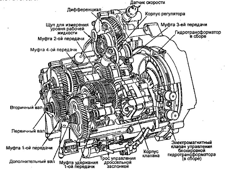
Shown is an automatic transmission with 7-position shift lever.
On boxes with 6 positions of the shift lever there are no parts related to the additional shaft.
Couplings
The 4-speed automatic transmission uses hydraulically controlled clutches to engage and disengage the transmission gears. When hydraulic pressure is applied to the clutch drum, the clutch piston moves. This compresses the friction discs and steel plates together, locking them so they do not slip. Power is then transmitted through the clutch pack to the hub gear.
When hydraulic pressure is released from the clutch pack, the piston relaxes the friction discs and steel plates and they are free to move relative to each other without transmitting power.
1st coupling
clutch 1 engages/disengages with gear 1 and is located at the end of the input shaft, just behind the right side of the cover. Clutch 1 is supplied with hydraulic pressure via an ATF tube inside the input shaft.
First Retention Clutch (7-position transmission)
This clutch is connected in first gear in position [1], to lock the overrunning clutch and provide engine braking. This clutch is located in the middle of the auxiliary shaft and receives pressure through it.
2nd coupling
the 2nd clutch engages/disengages with the 2nd gear and is located in the center of the input shaft. The 2nd clutch is connected end-to-end with the 4th clutch. The 2nd clutch is supplied with hydraulic pressure through the input shaft, via a line connected to the internal hydraulic circuit,
3rd coupling
the 3rd clutch engages/disengages with the 3rd gear and is located at the end of the secondary shaft opposite the right side of the cover. The 3rd clutch is supplied with hydraulic pressure by the ATF supply pipe inside the countershaft shaft.
4th clutch
the 4th clutch engages/disengages with the 4th gear and is located in the center of the input shaft. The 4th clutch connects with the 2nd clutch. The 4th clutch is supplied with hydraulic pressure by the ATF supply pipe inside the input shaft.
Overrunning clutch
The overrunning clutch is located between the parking gear and the 1st gear on the secondary shaft. The 1st gear on the secondary shaft provides the outer race surface and the parking gear provides the inner race surface. The overrunning clutch is locked when power is supplied from the 1st gear on the primary shaft to the 1st gear on the secondary shaft, the 1st clutch and gears remain engaged in 1st, 2nd, 3rd and 4th gears and in the [D4], [D3J or [2] position. The overrunning clutch is disengaged when the 2nd, 3rd or 4th clutch/gears are engaged. This occurs because the increased rotational speed of the gear on the secondary shaft exceeds the 1st gear drive speed.
Accordingly, the overrunning clutch moves freely with the 1st clutch still engaged.
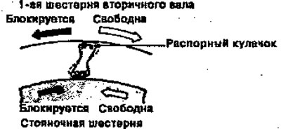
Note: View from the right cover burner
Power flow
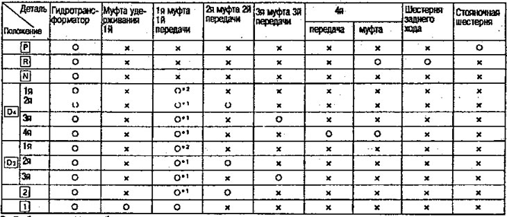
- A: It works x: It doesn't work
- *1: Although the 1st clutch engages, power is not transmitted as the overrunning clutch slips.
- *2: The overrunning clutch engages during acceleration and slips during deceleration.
Note: [1] Position and 1st holding clutch apply to 7-position transmission.
![Note: [1] Position and 1st holding clutch apply…](https://www.hondabook.ru/img/civic/3654.jpg)
Shown is an automatic transmission with 7-position shift lever.
On boxes with 6 positions of the shift lever there are no parts related to the additional shaft.
[The article is based on information from the website: HONDABOOK.ru]