
Examination
Note: Lockout control solenoid valves A and B must be removed/replaced as a unit.
1. Disconnect the 2K connector from the A/V solenoid valve assembly.
2. Measure the resistance between pin No. 2 (solenoid valve A) connector of the system control solenoid valve and the housing, and between the 1st contact (solenoid valve B) and body.
Standard: 14 - 25 Ohm
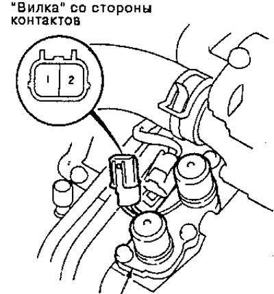
A/B lockout control solenoid valve assembly
3. Replace the solenoid valve assembly if resistance is not within specification.
4. If the resistance is within the standard, connect pin #1 of the solenoid valve connector to the battery positive terminal. A clicking sound should be heard. Connect pin #2 to the positive terminal of the battery. A clicking sound should be heard. Replace valve assembly if clicking sound is not heard
Replacement
1. Remove the A/B solenoid valve mounting bolts and assembly.
Note: Make sure you remove or replace the A and B solenoid valves as an assembly.
2. Check for dust in the fluid passages of the solenoid valve and replace it as a unit if necessary.
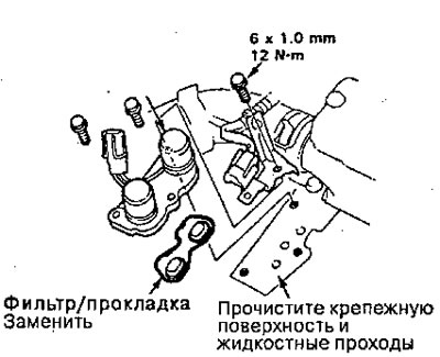
A/B lockout control solenoid valve assembly
3. Clean the mounting surface and fluid passages of the solenoid valve assembly and install a new A/B solenoid valve with a new filter.
4. Check the connector for rust, dirt or oil, and connect securely.