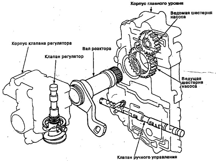
The ATF pump is driven through splines on the right end of the torque converter, which is connected to the engine. Fluid passes through the regulator valve to maintain rated pressure through the main level body to the manual control valve directing pressure to each clutch.
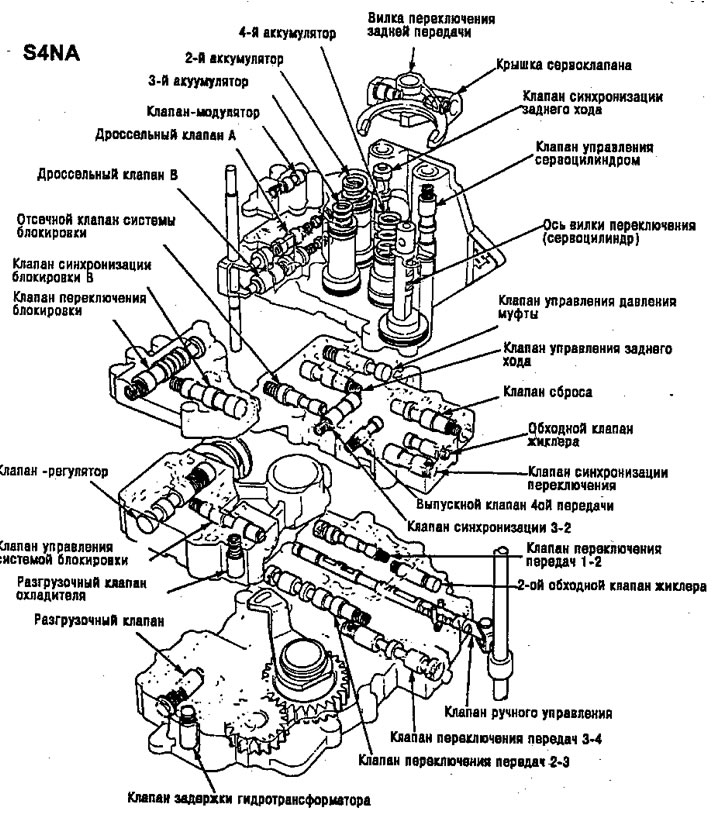
S4NA
ATF Pump (S4NA)
The external gear ATF pump consists of a housing combined with a main level housing, a drive gear, a driven gear and a pump shaft. The ATF pump is installed on the torque converter housing, the pump is driven by the torque converter pump (directly connected to the engine) through the drive gear, which is connected to the shaft by splines. The gears are located in the housing, the input and output lines, and the torque converter line are also located in the housing.
Control valve
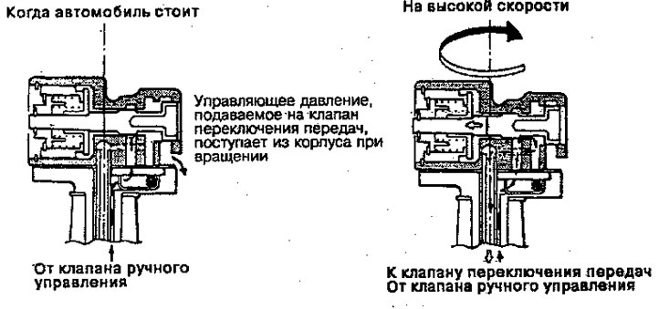
The control valve regulates hydraulic pressure depending on vehicle speed. The control valve maintains high pressure when the vehicle speed is high and low pressure when the vehicle speed is low, the pressure produced by the control valve acts on the gear shift valve and is one of the two causes of automatic speed change. The control valve gear, being in mesh with the driven gear of the main gear, rotates the valve shaft, regulating it using centrifugal force. The control valve receives line pressure. Generation of control pressure, regulates the line pressure. This pressure is regulated by the balance of centrifugal forces using the first second and third weights centered around the axis of rotation. The force arises as a result of the difference in the diameters of the control valve and the number of revolutions, depending on the speed of the vehicle. The control pressure increases as the vehicle speed increases.
Valve regulator
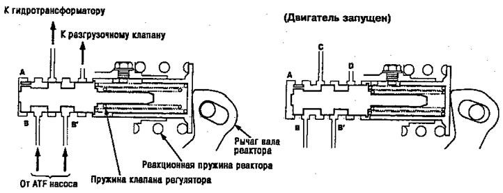
The regulator valve maintains constant hydraulic pressure sent from the ATF pump to the hydraulic control system, while at the same time transferring fluid to the lubrication system and torque converter.
The liquid passes through lines B and B*. The fluid entering through line B then passes through the hole in valve A, pushing the regulator valve to the right. In accordance with the amount of hydraulic pressure in line B, the position of the valve will change, and thus the amount of fluid passing through lines B* and D will change. This process continues while maintaining line pressure.
Note: when the concept is used"right" or "left", meaning the direction in accordance with the figure below.
(With the engine off.)
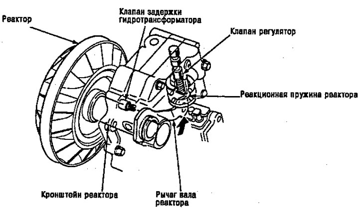
Reactor hydraulic pressure control
The increase in hydraulic pressure in accordance with the torque is carried out using a regulator valve that uses the reaction torque of the reactor. The reactor shaft fits into the reactor splines and its end comes into contact with the tip of the regulator spring. When the vehicle is accelerating or going uphill (torque converter range), the reaction torque acts on the reactor shaft, and the lever pushes the tip of the regulator spring towards the arrow, in proportion to the reaction. The spring compresses and the valve moves, increasing the regulated pilot or line pressure. The line pressure is maximum when the reactor response is maximum.