HondaBook.ru
Auto companies Volkswagen Auto companies Ford Auto companies Lada Auto companies Skoda Auto companies BMW Auto companies Mazda Auto companies Peugeot
English Русский
Български
Беларускі
Український
Српски
Hrvatski
Română
Polski
Slovenský
Magyar
Bookmark Contacts Sitemap   


Accord Civic Fit / Jazz CR-V HR-V Others Articles
Civic 3 and 4 (1983-1991) Civic 5 and 6 (1991-2000) Civic 6 (1995-2000) Civic 7 (2000-2005) Civic 8 (2005-2011)

Front brake pads (Honda Civic 5)

  • Main
  • Honda Civic
  • 5 (1991-2000)
  • Chassis and running gear
  • Brake system
  • Front brake pads
0

Inspection and replacement


There are 6 types of front brake mechanisms, which can be classified into 3 groups (type A, type B and type C). Check the type of brake mechanism before starting work because the operating procedure differs depending on the type of mechanism.

A type: Nissin mechanism

B type: Akebono mechanism (for 14" and 15" wheel rims)

With type: Akebono mechanism (for 13" wheel rims)

Note:
  • Nissin movement and Akebono movement can be identified by the Nissin mark applied to the Nissin movement case.
  • Front brake disc OD for 14" and 15" wheel rims: 262 mm
  • Front brake disc OD for 13" wheel disc: 240 mm


Type A and Type B:

Note: For type C operating procedure, see below.


Warning
  • Never use an air hose or dry brush to clean brake components.
  • Use a vacuum cleaner to avoid inhaling brake dust.


1. Loosen the front wheel nuts slightly, then raise the car and secure it on safe stands.

2. Remove the brake hose fasteners from the steering knuckle.

3. Remove the mechanism bolt and turn the mechanism over.
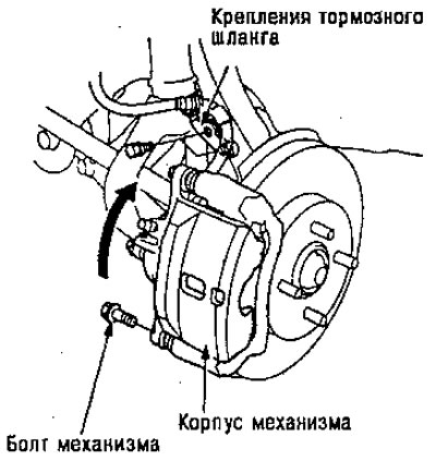
3. Remove the mechanism bolt and turn the…


Note: Check the hoses and axle boots for damage or destruction.


4. Remove the brake pad plates, pad holders and pads.


Note: When the brake mechanism is equipped with an outer plate, replace the plate together with the shoe as an assembly.
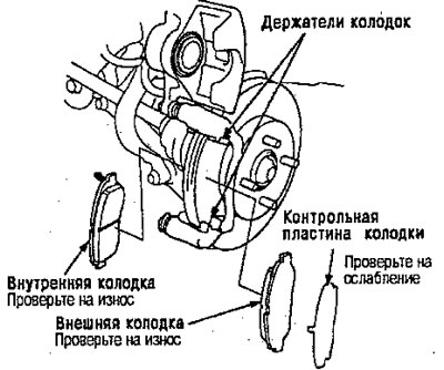

Note: When the brake mechanism is equipped with…


5. Using a caliper, measure the thickness of each brake lining.

Brake lining thickness:

Standard

For 13" wheel rim: 8.5-9.5 mm

For 14" and 15" wheel rims: 9.5-10.5 mm

Operating values: 1.6 mm

Operating values: 1.6 mm


Note: Measurements do not include the thickness of the pad mounting plate.


6. If the brake lining thickness is less than the service values, replace the entire front pads.

7. Clean the mechanism thoroughly, remove rust and check for grooves and cracks.

8. Check the brake disc for damage and cracks.

9. Install the brake shoe holders.
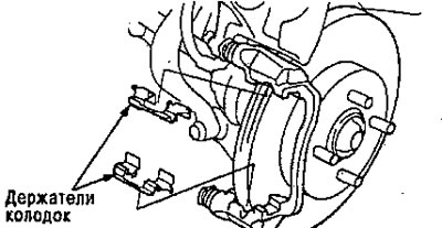
9. Install the brake shoe holders.


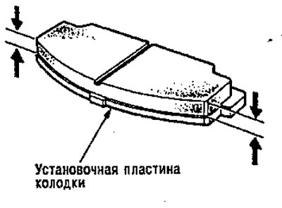
10. Apply grease to the points indicated by the arrows in the figure below.


Note: Use the pad grease included in the kit or M77 grease (Molikot) and apply a thin layer of grease even to the specified points.

  • Piston and contact surface of the inner shoe
  • The shoe and the contact surface of the mechanism support
  • External cover and contact surface of the mechanism housing. Mechanism with a control plate of the external shoe
  • Control plate of the shoe and the contact surface of the outer shoe Control plate of the shoe and the contact surface of the mechanism body
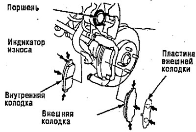
Control plate of the shoe and the contact surface…


11. Install the brake pads and pad plates correctly.

Warning
  • When reusing pads, always install them in their original position to prevent loss of braking effectiveness.
  • Contaminated brake discs or pads reduce braking efficiency. Remove grease from discs and pads.


Note: Install the pad with the wear indicator on the inside.


12. Push the piston in until the mechanism sits on top of the shoes. Make sure the piston boot is in a position to prevent damage when turning over.
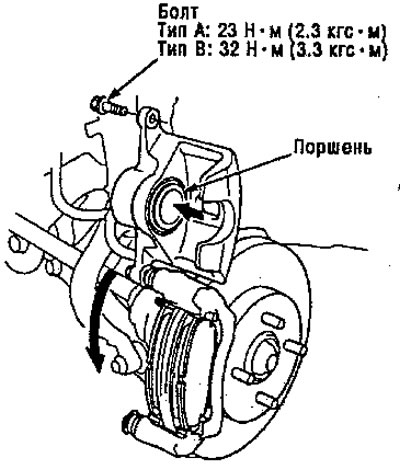
12. Push the piston in until the mechanism sits…


13. Turn the mechanism down into place, then install the bolt and tighten it.


Warning: Be careful not to damage the axle boot when rotating the mechanism downwards.


14. Install the brake hose brackets to the steering knuckle.

Note: Inspect the brake hose for snagging or twisting.


15. Press the brake pedal several times to make sure the brakes work, then test drive the car.

Note: Applying the brakes may require more pedal travel immediately after replacing the pads. A few pumps of the brake pedal will restore normal pedal travel.


16. After installation, check hoses and line connections or connectors for leaks and tighten if necessary.

Type C:

Warning
  • Never use an air hose or dry brush to clean brake components.
  • Use a vacuum cleaner to prevent dust from entering your respiratory tract.


1. Loosen the front wheel nut slightly, then raise the car and secure it on safe stands.

2. Remove the brake hose mount from the steering knuckle.

3. Remove bolt B from the mechanism and turn the mechanism upside down.
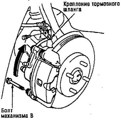
3. Remove bolt B from the mechanism and turn the…


Note: Check the hoses and axle boots for damage or destruction.


4. Remove the brake pad plate, pad holders and pads,

Note: When replacing the pad, replace the plate with the pad as a set.
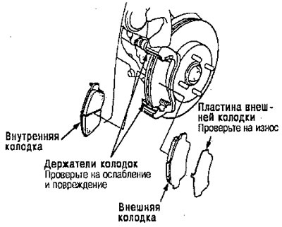


Note: When replacing the pad, replace the plate…


5. Using a caliper, measure the lining thickness of each brake shoe.

Brake lining thickness:
  • Standard: 8.5-9.5 mm
  • Operating values: 1.6 mm


Operating values: 1.6 mm


Note: Measurements do not include the thickness of the pad mounting plate.


6. If the brake lining thickness is less than the service value, replace the front pads as a set.

7. Clean the mechanism thoroughly, remove rust and check for grooves and cracks.

8. Check the brake disc for damage and cracks.

9. Install the brake shoe holders.
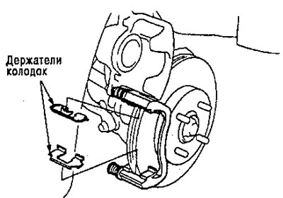
9. Install the brake shoe holders.


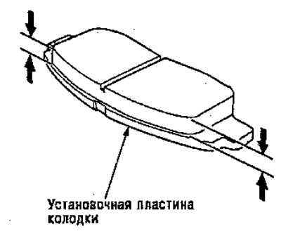
10. Apply grease to the points indicated by the arrows in the figure below.


Note: Use the pad grease included in the kit or M77 grease (Malikot) and apply a thin layer of grease even at the designated points.

  • Piston and contact surface of the inner shoe
  • Shoe and contact surface of mechanism bracket
  • External shoe and contact surface of the mechanism body
  • Outer shoe plate and outer shoe contact surface
  • The outer shoe plate and the contact surface of the mechanism body
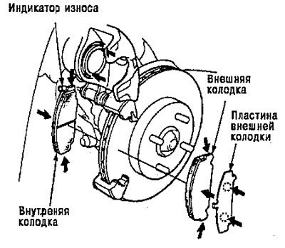
The outer shoe plate and the contact surface of…


11. Install the brake pads and pad plate correctly.

Warning
  • When reusing pads, always install them in their original position to prevent loss of braking effectiveness.
  • Contaminated brake discs or pads reduce brake performance. Remove grease from discs and pads.


Note: Install the pad with the wear indicator on the inside.


12. Push the piston in until the mechanism sits on top of the shoes. Make sure that the piston boot is in a position that prevents damage when turning the mechanism down.
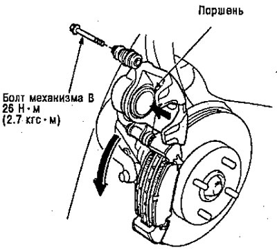
12. Push the piston in until the mechanism sits…


13. Turn the mechanism down into place, then install bolt B and tighten it.

14. Install the brake hose bracket onto the steering knuckle.

Note: Inspect the brake hose for pinching or twisting.


15. Press the brake pedal several times to make sure the brakes work, then test drive the car.

Note: Applying the brakes may require more pedal travel immediately after replacing the pads. A few pumps of the brake pedal will restore normal pedal travel.


16. After installation, check hoses and line connections or connectors for leaks and tighten if necessary.
This article is available at: russian, bulgarian, belarusian, ukrainian, serbian, croatian, romanian, polish, slovak, hungarian
This information has been verified: Mikhail Kopasov
Share with friends:
◀ Previous
Civic 5 and 6: Brake system
Next ▶

Parking brake
Brake pedal
Front brake disc
Front brake mechanism
Assembly — Type A and Type B
Assembly — type C
Master Brake Cylinder — Brake Booster
See also other articles from Honda manuals:
Front Disc Brake Pads — Inspection Honda Accord 3 (1985-1989)
Replacing the front brake pads Honda Fit 1 (2001-2008)
Front disc brake pads Honda CR-V 1 (1995-2001, petrol)
Front Brake Pads — Checking and Replacing Honda HR-V 1 (1998-2006, petrol)
Front Brake Pads — Checking and Replacing Honda Avancier 1 (1999-2003, petrol)
Link in different formats to this article
Comments and feedback from visitors
No comments yet


How much will 48 + 34 ?


Civic 8 (2005-2011) 
  • General information
  • Technical data
  • Governing bodies
  • Driving and maintenance
  • Power unit
  • Gasoline engines (L13A)
  • Gasoline engines (R18A)
  • Diesel engines (N22A)
  • Cooling and lubrication (L13A)
  • Cooling and lubrication (R18A)
  • Cooling and lubrication (N22A)
  • Injection system (gasoline)
  • Injection system (diesel)
  • Toxicity reduction system
  • Troubleshooting
  • Transmission
  • Clutch and drive shafts
  • Mechanical gearbox
  • Chassis and running gear
  • Suspension and wheels
  • Steering
  • Brake system
  • Body and interior
  • Exterior (external elements)
  • Doors, locks and windows
  • Electrical equipment
  • Equipment and devices
  • Headlights and lighting
  • Power devices
  • Electrical circuits
Civic 7 (2000-2005) 
  • General information
  • User manual
  • Maintenance
  • Power unit
  • Engines D15B and D17A
  • K20A Engines
  • Overhaul engine
  • Cooling system
  • Lubrication system
  • Fuel injection system
  • Toxicity reduction system
  • Engine electrical equipment
  • Transmission
  • Clutch
  • Manual gearbox
  • Automatic gearbox
  • Variator (CVT)
  • Drive shafts
  • Chassis and running gear
  • Car suspension
  • Steering
  • Brake system
  • Body and interior
  • Exterior (external elements)
  • Interior (internal elements)
  • Doors, locks and windows
  • Heater and air conditioner
  • Manual air conditioner
  • Automatic air conditioner
  • Security system
  • Electrical equipment
  • Equipment and devices
  • Headlights and lighting
  • Windscreen wipers
  • Audio system
  • Electrical diagrams
Civic 6 (1995-2000) 
  • General information
  • Introduction to guide
  • User manual
  • Maintenance
  • Power unit
  • Engine in car (Civic)
  • Engine in car (Integra)
  • Engine overhaul
  • Cooling and heating
  • Power and exhaust systems
  • Engine electrical equipment
  • Engine management systems
  • Transmission
  • Manual gearbox
  • Automatic transmission (AT/CVT)
  • Clutch and drive shafts
  • Chassis and running gear
  • Brake system
  • Car suspension
  • Steering
  • Body and interior
  • Exterior (external elements)
  • Interior (internal elements)
  • Doors, locks and windows
  • Electrical equipment
  • Equipment and devices
  • Electrical circuits
Civic 5 and 6 (1991-2000) 
  • Power unit
  • SOHC engines
  • DOHC engines
  • Engine overhaul
  • Cooling and lubrication system
  • Intake and exhaust system
  • Fuel injection system (SOHC)
  • Fuel injection system (DOHC)
  • Carburetor
  • Transmission
  • Clutch
  • Manual gearbox S4C
  • Manual gearbox S40
  • Automatic gearbox
  • Drive shafts
  • Chassis and running gear
  • Car suspension
  • Steering
  • Brake system
  • Body and interior
  • Body elements
  • Heater and air conditioner
  • Electrical equipment
  • Power devices
  • Equipment and instruments
  • Electrical circuits
Civic 3 and 4 (1983-1991) 
  • General information
  • Maintenance
  • Power unit
  • Engine in a car
  • Engine overhaul
  • Cooling system
  • Power and exhaust system
  • Engine electrical equipment
  • Emission control system
  • Transmission
  • Mechanical gearbox
  • Automatic gearbox
  • Clutch and drive shafts
  • Four-wheel drive
  • Chassis and running gear
  • Brake system
  • Car suspension
  • Steering
  • Body and interior
  • Body elements
  • Electrical equipment
  • Equipment and devices
  • Electrical circuits
HondaBook.ru © 2018–2026 • Mobile version • Sitemap: EN BG BY UA RS HR RO PL SK HU • Feedback • Driver Information • Search system • Bookmark
Accord 3 (1985-1989) • Accord 6 (1997-2002) • Civic 3 and 4 (1983-1991) • Civic 5 and 6 (1991-2000) • Civic 6 (1995-2000) • Civic 7 (2000-2005) • Civic 8 (2005-2011) • Fit 1 (2001-2008) • CR-V 1 (1995-2001) • CR-V 2 (2002-2006) • HR-V 1 (1998-2006) • Avancier 1 (1999-2003) •
 
This website uses cookies to ensure proper functioning. By clicking "OK," you agree.