
Removal
1. Access to the clutch components is usually sufficient after removing the gearbox.
2. Remove the gearbox (see Chapter 7A). The engine must have additional temporary support at all times while the gearbox is removed.
3. The clutch fork and release bearing remain in the gearbox.
4. To hold the basket while unscrewing the flywheel mounting bolts, insert a suitable tool into the disk hole.
5. Carefully inspect the clutch basket and flywheel. Find the identification marks (usually the letters X or O painted in white). If no marks are found, make your own mark.
6. Carefully loosen the mounting bolts. Work in a criss-cross pattern until the pressure plate spring is completely released. Remove the basket and disc.
Inspection
7. Usually all clutch problems are related to the drive plate. However, attention is required to all components of the unit.
8. Inspect the flywheel for cracks, burns, grooves and other defects. Light defects can be detected by turning the flywheel to the recommended surface finish.
9. Inspect the disc linings. They should protrude under the rivets by at least 1.5 mm. Check for the presence of all rivets, warping, cracks in the linings and hub; integrity of springs and absence of other defects.
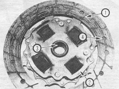
Fig. 5.9 Clutch disc: 1 - lining (wear); 2 - springs (cracks, deformation); 3 - bushing (the splines must be free of wear, the sides smooth); 4 - rivets (the heads must be recessed).
10. When replacing the disc, we strongly recommend replacing the release bearing.
11. Inspect the surface of the pressure plate and the diaphragm spring pins. If the pressure plate has grooves or appears to be badly worn, replace it. Light blemishes can be removed with sandpaper.
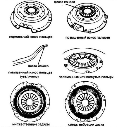
Fig. 5.11 Examples of pressure plate wear
Installation
12. Before installation, wipe the surfaces of the flywheel and pressure plate. Do not allow oil or grease to come into contact with these surfaces. When assembling the clutch, keep your hands clean.
13. Install the clutch disc and basket in place. Make sure the clutch disc is oriented correctly (there should be either marks or the disc springs are facing the gearbox).
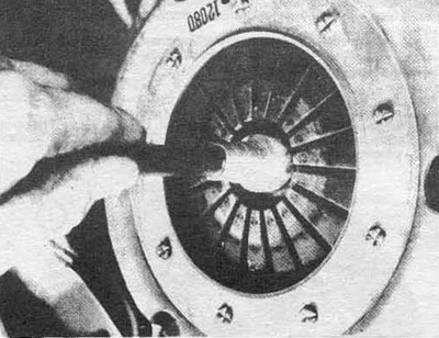
Fig. 5.13 Centering the clutch along the guide
14. Fit the basket-to-flywheel mounting bolts and tighten them by hand.
15. Center the disc using the special tool. Tighten the bolts in a crisscross pattern. The tightening step should be uniform to avoid distortion of the basket. The final tightening force is specified in the specification. Remove the adjusting tool (see fig. 5.13).
16. Apply high-melting grease to the inner groove of the release bearing (see Section 4), the contact surface of the fork and shaft.
17. Install the release bearing (see Section 4).
18. Install the box and assemble the car.
[Original published on this resource: HONDABOOK.ru]