Checking valves
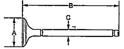
Check the geometric dimensions of the valves.
L1FOR:
Inlet valve:
A - 31.85-32.15 mm
B - 118.05-118.65 mm
WITH:
- nominal - 5.48-5.49 mm
- maximum - 5.45 mm
Exhaust valve:
A - 27.85-28.15 mm
B - 117.76-118.36 mm
WITH:
- nominal - 5.45-5.46 mm
- maximum - 5.42 mm
L15A:
Inlet valve:
A - 27.35 - 27.65 mm
B - 118.05 -118.65 mm
WITH:
- nominal - 5.48-5.49 mm
- maximum - 5.45 mm.
Exhaust valve:
A - 22.85 - 23.15 mm
B - 117.25-117.85 mm
WITH:
- nominal - 5.45 - 5.46 mm
- maximum - 5.42 mm
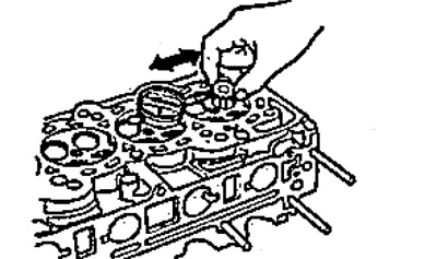
Checking clearance between valve and valve guide
1. Pull the valve out of the cylinder head approximately 10 mm.
By moving the valve back and forth, determine the gap between the valve and the valve guide with the indicator.
- If the measured value exceeds the maximum, check with a new valve.
- If the value obtained corresponds to the maximum, replace the valve with a new one.
- If the measured value with the new valve exceeds the maximum, go to the next step.
Inlet valve:
- nominal clearance - 0.04 - 0.10 mm
- maximum clearance - 0.16 mm
Exhaust valve:
- nominal clearance - 0.10 - 0.16mm
- maximum clearance - 0.22 mm
2. Measure the inside diameter of the valve sleeve.
Valve Boss Inner Diameter:
- nominal - 5.51- 5.53 mm
- maximum - 5.55 mm
3. Subtract the measured valve stem outside diameter from the valve sleeve inside diameter.
Take measurements at three different locations on the valve and bushing.
The difference between the largest bushing diameter and the smallest valve stem diameter must not be greater than the maximum clearance.
Inlet valve:
- nominal clearance - 0.02 - 0.05mm
- maximum clearance - 0.08 mm
Exhaust valve:
- nominal clearance - 0.05 - 0.08 mm
- maximum clearance - 0.11 mm
Valve Sleeve Replacement
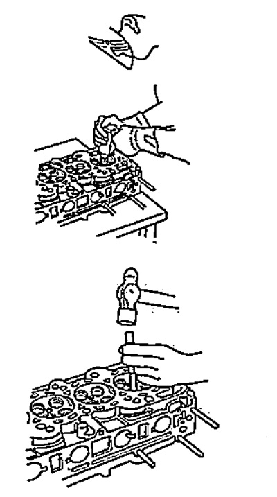
1. To carry out the following operations, you will need a hammer and a special tool.
2. Select the required valve sleeves and chill them in the freezer for about an hour.
3. Heat the cylinder head on the hotplate to approximately 150°C. Do not heat the cylinder head above the specified temperature, as this may loosen the seating of the valve seats.
4. Using a special tool and a pneumatic hammer, knock out the bushing towards the combustion chamber by 2 mm. This will remove carbon deposits and allow for easier removal,
5. Turn over the cylinder head and knock out the bushings towards the side of the camshaft. The axis of the hammer must coincide with the axis of the sleeve.
6. If the bushing does not come out, drill through it with an 8 mm bit and try again. Drill the bushing only as a last resort, as if it breaks, damage to the cylinder head may occur.
7. Remove the bushings from the freezer.
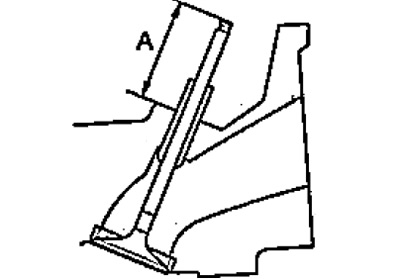
8. Apply fresh engine oil to the outside of the bushing. Install the bushings on the block head from the side of the camshaft, using a special tool, press the bushing to the required height. If you need to install 16 bushings, make sure that the head of the ball is heated.
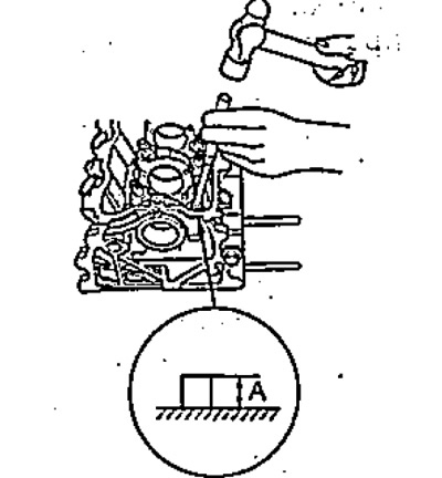
- Installation height "A" - 15.85- 16.35 mm
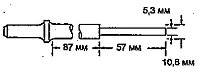
9. Lubricate the reamer and bushing with cutting fluid.
10. Turning the reamer clockwise, ream the bushing hole along its entire length.
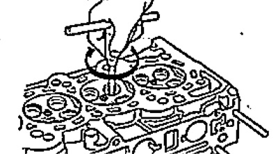
11. Rotate the reamer clockwise to remove it from the sleeve.
12. Thoroughly clean the bushings from machining products.
13. Check clearance. Make sure the valve moves in the guide without excessive force.
Valve seat repair
1. Before machining the valve seat, make sure that the gap between the guide sleeve and the valve is within specification.
2. Using a 45°reamer, grind the valve seats, removing only a minimal amount of metal to clean the seats.
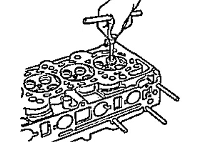
3. The corners of the top and bottom edges of the chamfer are shown in the figure.
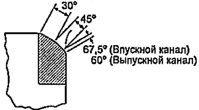
4. Using light pressure, make one pass with a 45°reamer to remove any burrs that may have appeared on previous passes.
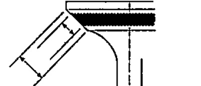
Bevel width:
Inlet:
- nominal - 0.850-1.150 mm
- maximum - 1.60 mm
Release:
- nominal - 1,250 -1,550 mm
- maximum - 2.00 mm
5. Check the seating of the valve. Apply a thin layer of white to the bevel of the valve. Press the valve against the seat, lift it up and hold against the seat for a while.
6. White should remain on the entire surface of the saddle exactly in the middle.
- If the contact patch is located too high on the valve face, then use cutters with a taper angle of 67.5°to regrind the seat (inlet) or 60° (release) and 45°.
- If the contact patch is too low on the valve face, use 30°and 45°taper cutters to regrind the seat.
Note: Finishing must be done with a 45°taper cutter.
7. Install the valves in the cylinder head and measure their installation height "A".
Inlet valve:
- nominal height - 46.1 - 46.5 mm
- maximum height - 46.8 mm
Exhaust valve:
- nominal height - 46.2 - 46.6 mm
- maximum height - 46.9 mm
If the installation height is greater than the maximum, replace the valve and check it again. If it is still above the maximum, replace the cylinder head.
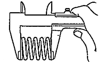
8. Check the valve springs. Use a caliper to measure the free length of the spring.
Spring free length:
- nominal - 50.52 mm
- maximum - 57.37 mm