
Note: before you start repairing CV joints, think about simply replacing them with new ones.
1. Remove the drive shaft from the vehicle (see Section 8).
2. Secure the axle in a soft jaw vise.
Inner CV joint and boot
Ball type
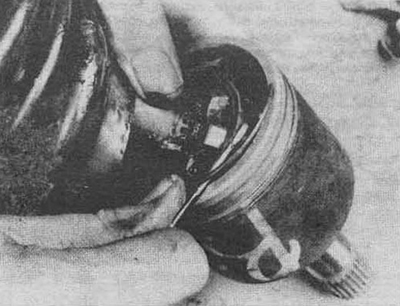
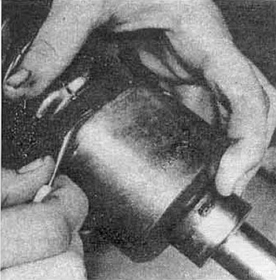
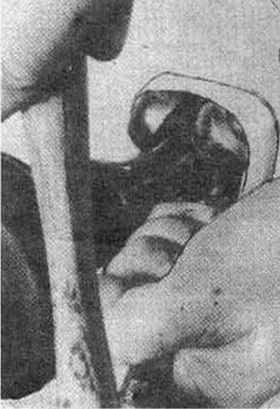
3. Cut the clips (see fig. 9.3a). Remove the boot (see fig. 9.36).
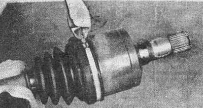
Pic. 9.3a Cut off the boot clips
Pic. 9.3b Remove the boot from the hinge cover
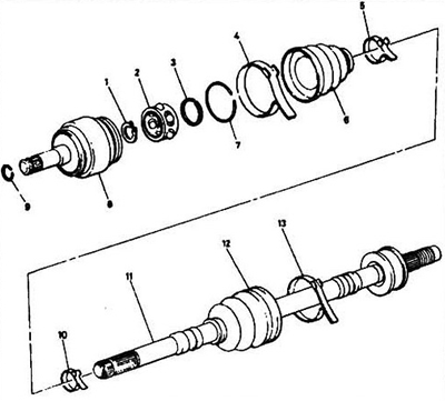
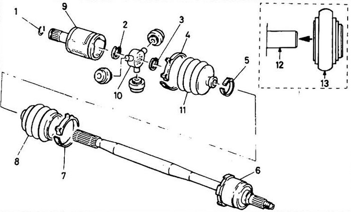
Pic. 9.3c Disassembly of the inner CV joint: 1 - retaining ring; 2 - separator; 3 - thrust ring; 4 - clamp; 5 - clamp; 6 - case; 7 - ring; 8 - hinge body; 9 - retaining ring; 10 - clamp; 11 - drive shaft; 12 - cover; 13 - clamp.
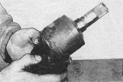
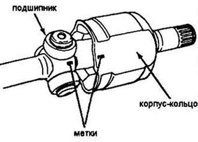
4. Mark the relative position of the inner and outer rings, the cage and the pivot shaft to assemble it in the same position.
Pic. 9.4 Marking the hinge parts
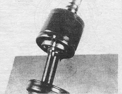
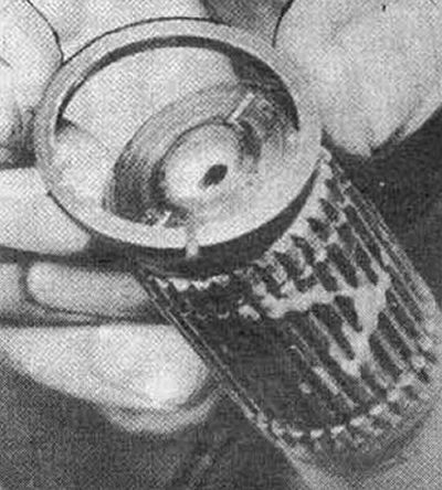
5. Remove the wire ring from the outer ring.
Pic. 9.5 Removing the wire ring
6. Remove the outer ring from the hinge.
7. Remove the stopper from the axle groove.
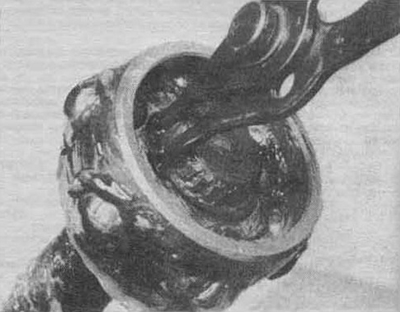
Pic. 9.7 Removing the stopper
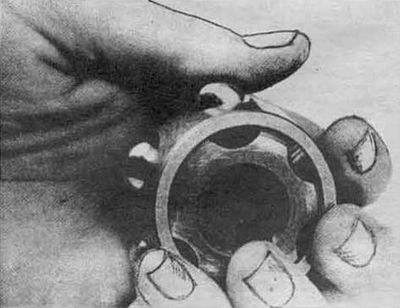
8. Pull the inner ring off the axle splines. Remove the thrust ring.
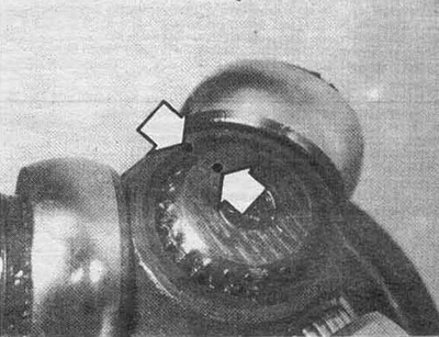
9. Use a screwdriver to remove the balls from the separator (see fig. 9.4). Carefully! Do not damage the inner ring, balls or cage.
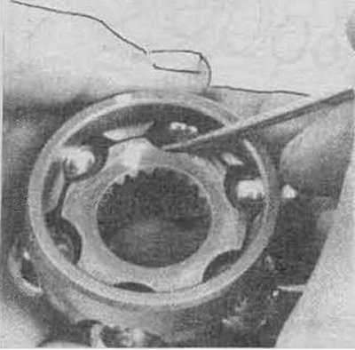
Pic. 9.9 Removing the balls: pry them off with a screwdriver
10. Rotate the teeth of the inner race to match the holes in the cage and separate them.
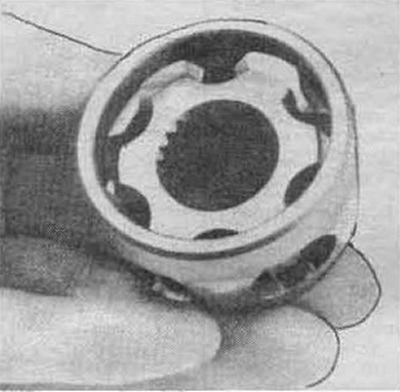
Pic. 9.10a Rotate the inner race until the teeth line up with the holes in the cage...
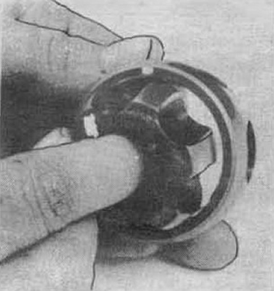
Pic. 9.10b... and separate the cage and inner ring
Inspection
11. Wash all parts. Inspect the cage and rings for pitting, nicks, cracks, or other damage. Lightening and polished areas are normal and do not affect the operation of the CV joint.
Assembly
12. Insert the inner ring into the cage so that the chamfer of the ring splines and the small diameter of the cage are on the same side.
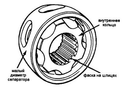
Pic. 9.12 Mutual position of inner ring and cage
13. By hand, press the balls into the separator
Pic. 9.13 Installing the balls in the cage
14. Wrap the splines of the drive shaft with electrical tape to prevent damage to the anther. Slide the boot onto the axle. remove the tape.
15. Install the restrictor ring in the axle groove. Install the inner ring/cage assembly. The large diameter of the cage should face outward.
16. Install retaining ring. Make sure the assembly is tight and secure.
17. Fill the outer ring and boot with the required amount of CV joint grease (usually sold with a new boot) Pack the entire joint with grease.
18. Slide the outer ring against the inner ring and install the wire clamp (see fig. 9.5).
19. Wipe off any excess grease from the outer ring boot groove. Install the small bore boot in its place on the axle. Pull the other end of the boot over the outer ring and. by rotating the ring, adjust the length of the hinge.
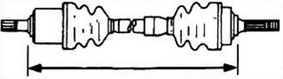
Pic. 9.19. Before installing the boot clamps, adjust the axle length. Dimensions are specified in the specification
20. After adjusting the shaft length, equalize the pressure in the boot by inserting a blunt screwdriver between the boot and the outer ring of the hinge.
Pic. 9.20 Pressure equalization inside the joint
21. Establish collars of fastening of anther. Make sure the axis length has not changed.
22. Install a new spring ring on the axle lug (see 8.10 a, b).
23. Install (see Section 8).
Finger type
Disassembly
24. Cut the boot clamps and slide it to the center of the axle.
Pic. 9.24 Assembling a typical finger-type inner CV joint assembly: 1 - spring ring; 2 - stopper; 3 - thrust ring; 4 - clamp; 5 - collar; 6 - external CV joint assembly; 7 - collar; 8 - anther; 9 - housing / outer ring of the inner hinge; 10 - cross; 11 - anther; 12 - finger; 13 - roller bearing.
25. Mark the relative position of the outer ring and the hinge cross, so that they can be returned to their place during assembly. Remove the case.
Pic. 9.25 Marking hinge parts
26. Remove the retaining ring from the end of the axle and mark the relative position of the cross and the axle (see fig. 9.26), remove the fixing bearings (see fig. 9.27).
Pic. 9.26 Relative position marks (arrows) cross and drive shaft
27. Use light hammer blows to remove the cross. Do not lose the bearing rollers and do not mix them.
Pic. 9.27 Removing the CV joint cross
28. Remove the thrust ring, pull off the old boot.
Inspection
29. Wash the hinge parts. Mark the roller bearings and their mounting locations. Disassemble the bearings one by one and wash them.
30. Inspect rollers, pins, bearings, and outer race for nicks, pitting, or other damage.
Assembly
31. Wrap the axle splines with electrical tape, pull the new boot onto the axle. Install the inner circlip.
Pic. 9.31 Fit the circlip firmly into its groove
32. Orient the cross on the marked marks and with light blows on the bronze drift, install the cross on the axis.
33. Install the outer retaining ring.
34. Apply CV joint grease to the inner ring of the cross bearings to hold the bearing rollers and put the bearings in their places on the cross.
35. Drive half of the total amount of grease into the polo / rings / CV joint housings. Put the body on the cross, centering it on the marks made earlier.
36. Install the boot on its seats and adjust the length of the axis (see fig. 9.19).
37. Equalize the pressure in the boot by inserting a screwdriver between the boot and the outer ring (see fig. 9.20).
38. Install new boot clamps and tighten them.
39. Install the drive shaft on the car (see Section 8).
External CV joint and boot
Disassembly
40. Guided by steps 3-10 (ball type) or 24-28 (finger type), remove the hinge from the axle and disassemble it.
41. If the drive axle is equipped with a dynamic damper, mark the relative position of the axle and the damper, cut the clamps and remove the damper.
42. Cut off the clamps of the CV joint boot, remove it.
Inspection
43. Thoroughly wash the joint. This will be quite difficult, since the hinge does not disassemble.
44. Bend the hinge as much as possible and inspect it for any damage. If damage is found, replace the drive room.
Assembly
45. Wrap the splines of the drive shaft with electrical tape and put a new boot on it (pic. 9.14). Stuff the boot with the grease from the repair kit, which remained after lubricating the hinge. Slide the boot over the hinge and tighten the clamps (pic. 9.21a, b).
46. Install a dynamic damper (if applied in this design). Make sure that the previously applied marks match. Install the retaining ring.
47. See steps 12-23 for the internal hinge rebuild process (ball type) or 31-38 (gimbal type). Installation of semiaxes is carried out according to the algorithm section 8.