
2. Turn the engine upside down.
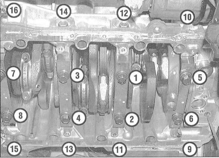
3. Give fixing bolts and remove covers of radical bearings and/or assembly of their bridge (4-cylinder engines).
4. If you have not already done this, remove the old main bearing shells from your beds in the block and covers. Wipe the beds with a clean, lint-free cloth - they should be immaculately clean.
Checking the operating clearances of main bearings
Note. Avoid touching the new bearing surfaces with bare hands to avoid unwanted contact of the bearings with traces of oil and chemicals that are always present on the fingers.
1. Wipe the backs of the new main bearing shells and insert the oil grooved ones (if provided) halves in their beds in the block. Insert the rest of the shell halves into the corresponding bearing caps. Make sure that the tongues of the liners enter the reciprocal landing grooves in the beds of the block and covers. The oil holes in the block must also be properly aligned with the holes in the liners.
Attention! Under no circumstances should you attempt to hammer an unfitted liner into your bed with a hammer. Do not lubricate the bearings at this stage!
2. When working on a V6 engine, remember that the thrust bearings (washers) installed on the third bearing. On 4-cylinder engines, the thrust bearing is number 4.
3. Wipe the surfaces of the bearings in the block and the crankshaft main journals with a clean, lint-free rag. Check the patency of the shaft oil holes, clean them if necessary. Any foreign particles contained in the oil paths will inevitably end up in the bearings.
4. Carefully wiped crankshaft carefully lay in the main bearings of the block.
5. Before finally installing the shaft, it is necessary to check the operating clearances in its main bearings.
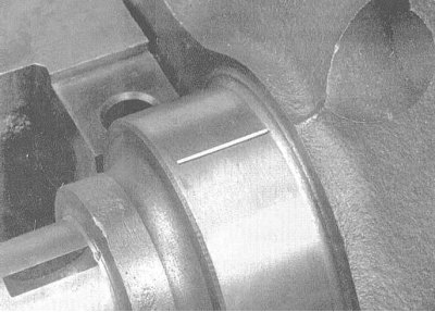
6. Cut the calibrated plastic wire from the Plastigage measuring set into lengths slightly shorter than the width of the bushings, and lay one piece of wire along each of the main shaft journals, parallel to their axis.
7. Wipe the surfaces of the liners in the covers and install the latter and / or their bridge assembly in their regular place. Try not to move the pieces of calibrated wire laid along the necks of the shaft. Lightly oil the threads of the mounting bolts and screw them in, fixing the covers.
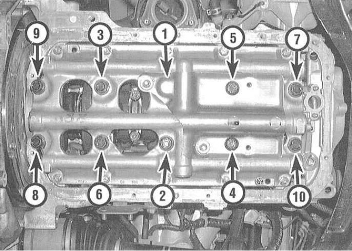
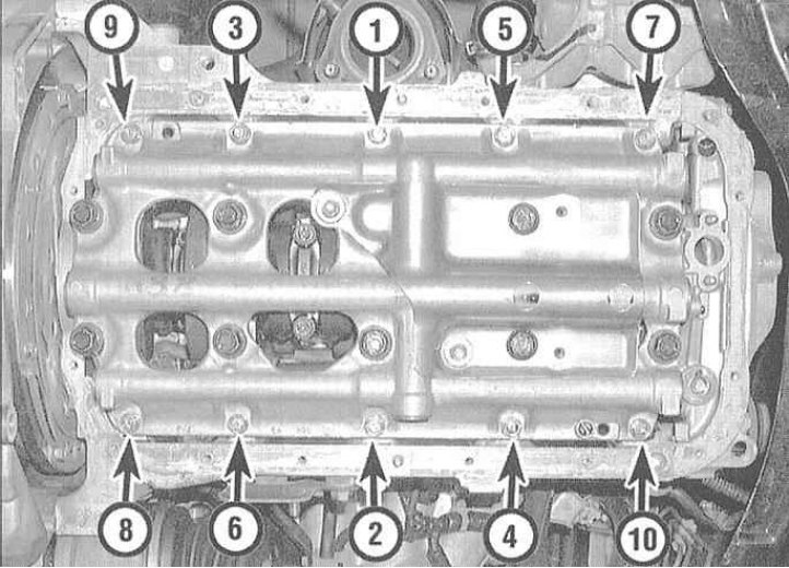
8. As indicated in one of the accompanying illustrations tighten the bolts securing the covers and/or their bridge in three stages to the required torque.
Attention! Do not allow the shaft to turn while tightening the fasteners!
9. Remove the bolts and carefully remove the main bearing caps and/or their bridge assembly. Place the removed covers in the order in which they are placed on the engine. Take care not to damage the flattened gauge wire and do not turn the shaft. If any of the covers cannot be removed, gently tap it to loosen it with a soft-faced hammer.
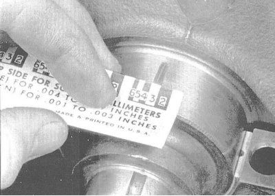
10. From the width of the flattened threads, measured on the scale printed on the packaging of the Plastigage kit, determine the operating clearances of the bearings. Compare the measurement results with the requirements of the Specifications.
11. If the gap is out of tolerance, the wrong size bushings may have been installed (see Section Checking the condition and selection of liners of main and connecting rod bearings of the crankshaft). Before looking for new liners, make sure that no dirt or oil has fallen under the ones inserted at this stage. If the calibrated wire is flattened at one end more than at the other, this indicates the presence of a neck taper (see Section Checking the condition of the crankshaft).
12. Carefully remove the gauge wire from the necks, scraping off all traces of it with some tool that is not too strong (like the edge of an old credit card). In extreme cases, you can use your own fingernail - the main thing is that there are no scratches or scratches on the surface of the necks / liners.
Final installation of the crankshaft
1. Carefully remove the crankshaft from the engine. Wipe the surfaces of the bearings in the block and evenly lubricate them with a thin layer of molybdenum-containing assembly motor grease. Don't forget to lubricate the thrust washers as well.
Attention! Try not to let grease get on the backs of the liners!
2. Make sure the crankshaft journals are absolutely clean, then lubricate (the same lubricant) seal-contact surfaces of the trunnions and carefully place the shaft into the block.
3. Wipe and lubricate the bearing surfaces in the block and covers.
4. Having turned the block with the shaft up, fill the connecting rod and piston assemblies into it (see Section Installing connecting rod and piston assemblies and checking the working clearances in the connecting rod bearings of the crankshaft).
Note. On 4-cylinder engines, reinstall the main bearing caps and tighten them with bolts without installing the connecting bridge yet. Tighten fasteners with a force of approximately 14÷27 Nm (if the bolts are too long to hold the caps alone, put washers under their heads). Fitting the caps will help to fix the shaft while installing the connecting rod and piston assemblies. Then the covers should be dismantled again, after which proceed to the procedure of paragraph 5.
5. Install the main bearing caps and their connecting bridge assembly on the engine. Remember that the arrows molded into the covers must point forward over the engine.
Attention! Don't forget to install thrust washers as well.
6. Lightly oil the threaded part and bottom surfaces of the heads of the fixing bolts, then screw in the latter and tighten them by hand. Tap the ends of the shaft trunnions with a hammer through a brass or lead drift to align the thrust washers and shrink the shaft before finally tightening the fasteners. Tighten the bolts of the covers and the connecting bridge to the required torque.
7. Rotate the crankshaft by hand several times, checking for freedom of rotation.
8. Finally, use a blade-type feeler gauge or DTI gauge to determine the shaft end play (see Section Removing the crankshaft). If the thrust surfaces of the shaft are not worn or damaged, and the bearings are replaced with new ones, the axial play must not exceed the allowable range.
9. Install a new crankshaft rear oil seal and bolt its holder to the block (see Section Installation of a back epiploon of a cranked shaft).