
2. Remove the connecting rod cap, remove the old bearings and wipe the surfaces with a clean, lint-free cloth.
Connecting rod bearing clearance control
3. Wipe the back of the upper bearing and install the bearing into the connecting rod. The bearing does not need to be lubricated at this stage.
4. Do the same with the connecting rod cover insert. Make sure. that the earbud retainers are installed in their sockets. When changing the clearance, it is extremely important that the bearing is completely free of oil.
5. Separate locks of piston rings, as it is specified in fig. 24.5.
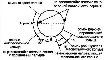
Pic. 24.5 The position of the locks of the rings on the piston
6. Put pieces of a plastic or rubber tube on the connecting rod bolts to prevent mechanical damage to the surfaces.
7. Lubricate the piston and rings with clean oil and squeeze the rings with a drift until the rings are firmly seated in the grooves.
8. Install the crankshaft to the bottom dead center of the corresponding cylinder and lubricate its walls with oil.
9. Orient the piston relative to the front of the engine according to the arrow or marks on the piston head, carefully insert the connecting rod and piston into the cylinder until it stops against the mandrel.
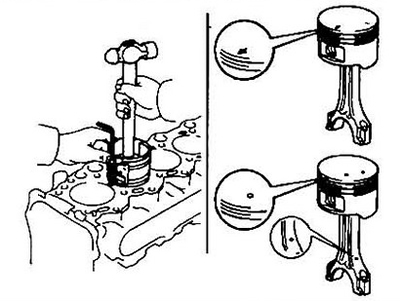
Pic. 24.9 Left. Piston installation. Use a wooden or plastic hammer handle.
On right. The small holes on the piston and connecting rod must be located on the side of the intake manifold. If there is an arrow on the piston, it must point to the front of the engine
10. Make sure that the mandrel is in full circumference contact with the surface of the block.
11. Using a hammer handle, lightly tap the piston into the cylinder until the connecting rod bearing is seated on the shaft. Be careful while installing the piston. so that the rings do not pop out of the mandrel. In this case, stop assembly immediately to avoid breaking the rings. And in any case, do not use force during installation.
12. The next step is to measure the clearance in the bearing.
13. Cut off a suitable piece of plastic gauge and place it on the shaft journal, parallel to its axis.
14. Clean the bearing surface in the cap. Remove the protective tubes from the bolts and install the connecting rod cap. Pay attention to the orientation of the cover.
15. Tighten cap in three steps to specification. Note: Use a thin-walled socket for tightening to avoid jamming the tool. Do not rotate the shaft when measuring clearance.
16. Remove the cap, being careful not to damage the caliber.
17. Measure the gap using the scale printed on the package of gauges and compare the result with that recommended in the specification.
18. In case of an unsatisfactory measurement result, re-measure the size of the shaft neck and select the desired insert. If the caliber has a different width at the ends, then the shaft neck is tapered (see point 18). Final installation of the connecting rod.
19. Carefully remove any remaining gauge from the neck.
20. Wipe the bearing surfaces and lubricate them with engine oil. Don't forget to put the protective caps on the connecting rod bolts when you lift the piston to access the top half of the bearing.
21. Set the piston against the bearing against the shaft, remove the protective caps, install the connecting rod cover and tighten the nuts in three steps.
22. Repeat the entire procedure for the remaining pistons.
23. Remember:
- A) the back surfaces of the inserts and the corresponding surfaces must be absolutely clean.
- b) do not swap pistons.
- V) the arrow on the piston should point to the front of the engine, the recesses should be on the side of the intake manifold.
- G) lubricate the cylinder walls with clean oil.
- d) lubricate the bearings after completing the clearance measurement procedure.
- e) correctly orient the connecting rod cap relative to its rod.
24. After completing the installation of the piston group, turn the engine by hand several times.
25. The final operation is the control of the axial clearance of the connecting rod, see section 12.
26. Install the main bearing caps (see section 22).