
Multi-point injection system
1. Start the engine and warm it up to operating temperature.
2. With the engine idling, remove the connectors from the injectors one by one - they are in order. If the engine speed does not change when the injectors are disconnected, do the work described below.
3. Using a voltmeter with high input resistance and with the engine running, check the voltage at the injector connector.
- a) If the voltage changes from zero to two volts, the injector is receiving enough electricity. Check the resistance of the injector solenoid winding (see step 4).
- b) if there is no voltage, check the additional resistance of the injector (see Section 15).
- c) if the additional resistance is normal, check the wires between the resistance and the injector and between the injector and the electronic module for short circuits, breaks or poor contact.
- d) if there is voltage, but the engine does not respond to the injectors being turned off, listen to the clicking sound of the injector valve opening. If the sound is the same as that of working injectors, check the resistance of the solenoid winding.
4. With the engine stopped, measure the resistance of the injector solenoid windings. If the resistance differs from the specification, replace the injector.
Replacement
5. Disconnect the negative cable from the battery.
6. Relieve the fuel pressure (see Section 2).
7. Remove the air filter (see Section 7).
8. Disconnect the injector connectors.
9. Disconnect the vacuum and fuel return hoses from the pressure regulator.
10. Disconnect the two ground wires from the exhaust manifold.
11. Disconnect the fuel hose from the fuel delivery line (nozzle holder).
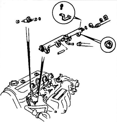
Fig. 15.11 Assembling the injector holder
12. Unscrew the mounting nuts and remove the holder and injectors.
13. Remove the injectors from the holder. Note the position of the damping and sealing rings.
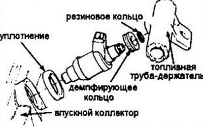
Fig. 15.13 Assembly of a multi-point injection system
Note: Replace the sealing and damping rings each time the injectors are removed.
14. Lubricate the new damping ring with engine oil and place it on the injector.
15. Lubricate the rubber ring with engine oil and place it on the nozzle. Install the nozzle on the holder.
16. Lubricate the seals with engine oil and insert it into the injector hole in the intake manifold.
17. Install the injectors into the manifold. Make sure that the marks on the injectors and manifold are aligned. Tighten the mounting nuts to the torque specified in the specification.
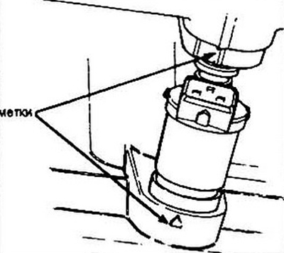
Fig. 15.17 Location of marks on the intake manifold and injector
18. The assembly procedure is the reverse of disassembly.
19. After completing the installation of the injectors, turn the ignition key until the fuel pump turns on, but do not turn off the starter. Turn off the pump. Repeat this two or three times and check for fuel leaks.
Two-point injection system
Control
20. Disconnect the electrical connectors from the upper (main) lower (auxiliary) injectors.
21. Measure the resistance of the injector solenoid windings and compare them with the specification data. If the resistance does not match, replace the injectors.
22. A more thorough inspection of the fuel system condition should be performed at a service station.
Replacement
23. Disconnect the negative cable from the battery
24. Remove the air filter housing from the throttle body,
25. Disconnect the electrical connectors from the injectors.
26. Loosen the holder screws and pull the injectors out of their sockets.
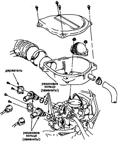
Fig. 15.26 Installing injectors (two-point injection scheme)
27. Lubricate the seals with engine oil, place them on the injector and mount the injectors into the valve bodies.
(The original can be found on the resource: hondabook)