
2. Place the jack under the lower arm.
Caution: The jack will sense the torsion bar reaction, carefully center the jack relative to the lower arm.
3. Remove the height adjustment nut.
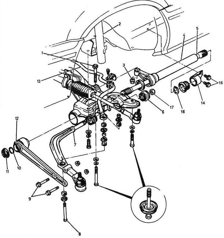
Fig. 5.3 Front suspension (models produced between 1984 and 1987): 1 - height adjustment bolt; 2 - rack; 3 - height adjustment nut; 4 - torsion bar pipe; 5 - torsion; 6 - Reactive lever bushing; 7 - jet lever; 8 - stabilizer mounting bolt; 9 - lower arm mounting bolt; 10 - torsion bar retaining ring; 11 - lid; 12 - lower arm; 13 - stabilizer; 14 - holder; 15 - Holder mounting bolts; 16 - locking ring; 17 - self-locking nut of the reaction lever.
4. In accordance with Figure 5.3, release the torsion bar tube.
5. Remove the torsion bar retaining ring (see fig. 5.3).
6. Remove the cover from the front end of the torsion bar and use light hammer blows to push the torsion bar shaft forward until the locking ring comes out, you can rock the lower arm while doing this. Remove the locking ring.
7. Mark the relative position of the torsion shaft and torsion tube.
8. Knock the torsion shaft out of the lower arm and remove it from the pipe. Use a wooden or plastic hammer.
9. Remove the pipe and its seal.
10. Inspect the torsion shaft. Wear of the teeth and cracks along the shaft are unacceptable - replace the torsion.
Installation
11. Lubricate the mounting surfaces of the torsion bar tube and the seal with grease, install the seal and tube on the steering and suspension coupler.
12. Lubricate the splines of the torsion shaft and insert it into the pipe in the direction from the center to the edge of the car.
13. Align the shaft and pipe position marks.
14. Push the torsion shaft into the lower arm splines far enough to install the locking ring. Keep in mind that the shaft spline outlet must match the lower arm spline bushing projection.
15. Install the retaining ring and the front end cover of the torsion shaft.
16. Install the retaining ring on the other side of the shaft.
17. Pack the bushing cover with grease and place it on the torsion shaft.
18. Install the torsion bar tube holders. Tighten the bolts.
19. Lubricate the height adjustment nut and tighten it by hand.
20. Install the wheels and wheel nuts, lower the vehicle and tighten the wheel nuts. Adjust the vehicle height. Adjusting the vehicle height.
21. Fill the fuel tank. Check the tire pressure, adjust if necessary.
22. Place the vehicle on a level surface.
23. Rock the car up and down to "land" the suspension.
24. Measure the distance between the top of the front wheel arch and the ground on both sides of the vehicle and record the result.
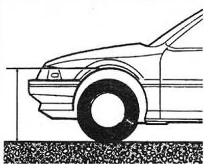
Fig. 5.24 Measuring the distance between the top of the front wheel arch and the ground
25. Compare the measurement result with the data specifications. If the result is outside the acceptable range, adjust the vehicle height.
26. To increase the height of the vehicle, tighten the adjusting nut; to decrease it, loosen it.
Note: One full turn of the adjusting nut changes the height by approximately 5 mm.
27. After the first adjustment, roll the car forward and backward by about half a body length, "seat" the suspension and take repeated measurements.
28. Repeat the operation until the measured height is within the desired range.