
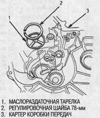
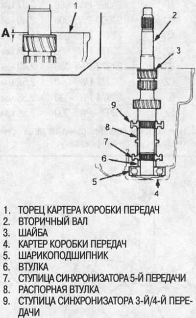
2. Install the 3rd/4th synchronizer hub, spacer sleeve, 5th synchronizer hub, sleeve and ball bearing to the secondary shaft, then install these components as an assembly into the transmission case.
3. Install the washer on the secondary shaft.
4. Measure the distance (A) between the end of the gearbox housing and the washer.
Note:
- Use a ruler and calipers.
- Take measurements in three places and average the values.
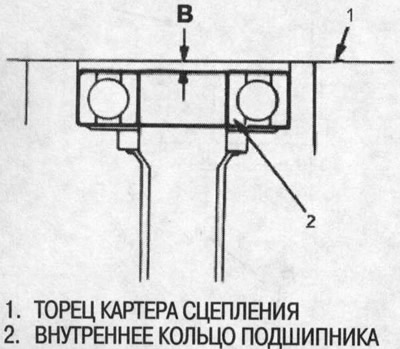
5. Measure the distance (B) between the end of the clutch housing and the inner ring of the bearing.
Note:
- Use a ruler and calipers.
- Take measurements in three places and average the values.
6. Select the required 78mm adjusting washer from the table using the following formula.
Formula for selecting a washer
From the measurements taken in points 4 and 5:
- 1. Add distance (B) (item 5) to distance (A) (item 4).
- 2. Subtract 0.93 from this number (which is the midpoint of the clutch housing bearing spring washer bend.
- 3. Take this number and compare it to the available washer sizes in the table.
FOR EXAMPLE:
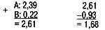
Try using a 1.68mm thick washer.
Adjusting washer 78mm
| Catalogue No | Thickness | |
| A | 23941-P16-000 | 1.20 mm |
| IN | 23942-P16-000 | 1.23 mm |
| WITH | 23943-P16-000 | 1.26 mm |
| D | 23944-P16-000 | 1.29 mm |
| E | 23945-P16-000 | 1.32 mm |
| F | 23946-P16-000 | 1.35 mm |
| G | 23947-P16-000 | 1.38 mm |
| N | 23948-P16-000 | 1.41 mm |
| I | 23949-P16-000 | 1.44 mm |
| J | 23950-P16-000 | 1.47 mm |
| TO | 23951-P16-000 | 1.50 mm |
| L | 23952-P16-000 | 1.53 mm |
| M | 23953-P16-000 | 1.56 mm |
| N | 23954-P16-000 | 1.59 mm |
| ABOUT | 23955-P16-000 | 1.62 mm |
| R | 23956-P16-000 | 1.65 mm |
| Q | 23957-P16-000 | 1.68 mm |
| R | 23958-P16-000 | 1.71 mm |
| S | 23959-P16-000 | 1.74 mm |
| T | 23960-P16-000 | 1.77 mm |
| and | 23961-P16-000 | 1.80 mm |
| V | 23962-P16-000 | 1.83 mm |
| W | 23963-P16-000 | 1.86 mm |
| X | 23964-P16-000 | 1.89 mm |
| U | 23965-P16-000 | 1.92 mm |
| Z | 23966-P16-000 | 1.95 mm |
| AA | 23967-P16-000 | 1.98 mm |
| AB | 23968-P16-000 | 2.01 mm |
| AC | 23969-P16-000 | 2.04 mm |
| AD | 23970-P16-000 | 2.07 mm |
| AE | 23971-P16-000 | 2.10 mm |
| F | 23972-P16-000 | 2.13 mm |
| AG | 23973-P15-000 | 2.16 mm |
| AN | 23974-P16-000 | 2.19 mm |
| AI | 23975-P16-000 | 2.22 mm |
| AJ | 23976-P16-000 | 2.25 mm |
| AK | 23977-P16-000 | 2.28 mm |
| AL | 23978-P16-000 | 2.31 mm |
| AM | 23979-P16-000 | 2.34 mm |
| AN | 23980-P16-000 | 2.37 mm |
7. Check the thrust clearance as follows:
Note: Measurement should be taken at normal room temperature.
1. Install the selected 78mm washer and oil transfer plate into the transmission housing.
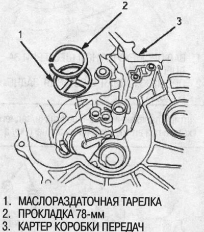
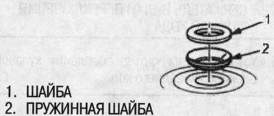
2. Install the spring washer and washer onto the ball bearing.
Note:
- Before installation, thoroughly clean the spring washer, washer and thrust washer.
- Install the spring washer, washer and thrust washer correctly.
3. Install the secondary shaft into the clutch housing.
4. Place the gearbox housing on the secondary shaft and on the clutch housing.
5. Tighten the transmission and clutch housings with several 8mm bolts.
Note: It is not necessary to apply sealant between the crankcases.
6. Tap the secondary shaft with a plastic hammer.
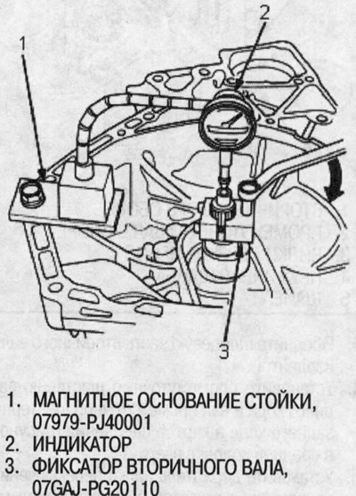
7. Place the secondary shaft base onto the secondary shaft.
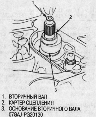
8. Secure the secondary shaft retainer to the secondary shaft as follows:
Note:
- Remove the secondary shaft retainer bolt and loosen the two hex head bolts.
- Place the retainer on the secondary shaft so that its edge faces the gearbox.
- Align the edge of the secondary shaft locking pin with the groove on the inner spline of the secondary shaft, then tighten the hex bolts.
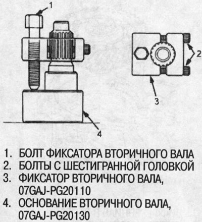
9. Fully seat the secondary shaft by tapping its end with a plastic hammer.
10. Screw in the secondary shaft retainer bolt until it just touches the wide area of the secondary shaft base.
11. Set the indicator to zero by resting its head against the end of the secondary shaft.
12. Turn the secondary shaft lock bolt clockwise, stop turning when the indicator reaches the end of its stroke. The indicator reading is the secondary shaft axial play.
Caution: Continuing to turn the secondary shaft lock bolt more than 60 degrees after the indicator needle stops moving may damage the transmission.
13. If the readings are within acceptable limits, the gap is normal.
If the readings differ from the norm, recheck the thickness of the adjusting shim.
- Standard: 0.11-0.18 mm