
Contents: If the "MIL" indicator lights up…⇊ If the MIL indicator does not light ⇊ If you cannot copy the DTC code ⇊ HDS System Memory Clear Command ⇊ Scan Tool Clear Command ⇊ Clearing DTCs ⇊ ECM reset ⇊ Cleaning procedure by reference…⇊ Diagnostic procedure (without HDS) ⇊ End of troubleshooting procedure…⇊
If the "MIL" indicator lights up (malfunction indicator)
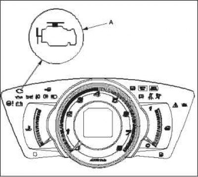
1. Start the engine and check the status of the MIL indicator A.
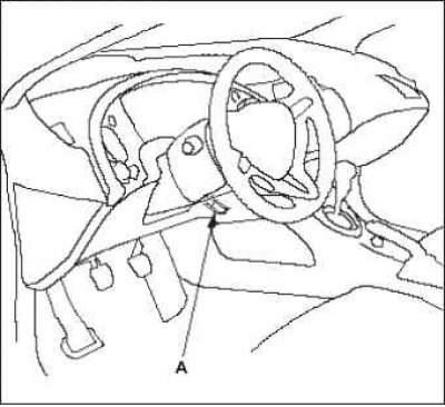
2. If the MIL remains on, connect the HDS to the Data Link Connector (DLC) A, located under the driver's side of the instrument panel.
3. Turn the ignition on by turning the key to the "ON" (II) position.
4. Check for a diagnostic trouble code (DTC) and record it if present. Also check the freeze data and/or on-board snapshot data and download the data found. Then refer to the DTCs and begin the appropriate troubleshooting procedure.
Note: Linked ("frozen") information indicates the engine operating conditions under which the first malfunction, misfire, or fuel injection system malfunction was detected.
The HDS can read DTCs, freeze data, current data and other engine control module (ECM) data.
For special operations, refer to the Owner's Manual that comes with the HDS.
5. If no DTCs are found, proceed to troubleshooting using the MIL indicator.
If the MIL indicator does not light
If the MIL does not come on but there is a problem with your vehicle, refer to the Symptom Troubleshooting.
If you cannot copy the DTC code
Some troubleshooting methods require you to clear the ECM memory and try to copy the DTC. If the fault is temporary and you cannot copy the code, do not continue the troubleshooting procedure. Continuing the procedure will lead to erroneous conclusions and possibly an unnecessary replacement of the ECM.
HDS System Memory Clear Command
The ECM memory stores various special data that allows the system to be adjusted even in the absence of electrical power, such as when the negative battery terminal or IGP fuse No.9 (15 A) is disconnected. When replacing memory parts, the fault information of the replaced parts must be erased using the command "CLEAR COMMAND" using the HDS diagnostic system ("Honda Diagnostic System").
The HDS diagnostic system has three memory cleanup commands for this purpose. These are "Erasing DTC codes", "Zeroing ECM data" and "Erasing the reference rotation position". The delete DTC fault Codes command erases all stored DTC codes, as well as recorded data and data from the onboard snapshot function. This operation must be performed using the HDS diagnostic system after the DTC code is reproduced during the troubleshooting process. The "Reset ECM data" command erases all stored DTC codes, fixed information, data from the onboard snapshot function, and all special data necessary to correct the system operation, with the exception of the reference spin position. If the Roll position (CKP) data in the ECM computer memory has been erased, you need to perform a training procedure based on the reference roll position (CKP). The Delete Pivot Reference Position (CKP) command erases only the reference pivot position (CKP) data. This command is used to eliminate a missed burnout or the SCR sensor reading.
Scan Tool Clear Command
If the scan tool clear routine commands are used, note that there is only one ECM/PCM clear setting that clears all commands at once (Reference Position Diagnostic Procedure, Idle Mode Diagnostic Procedure, Freeze Frame Data, On-Board Snapshot Data, and DTCs). After clearing all commands, perform the procedures in the following order: ECM Idle Mode Diagnostic Procedure; complete Kinetic Position (CKP) diagnostic procedure.
Clearing DTCs
1. Clearing the DTC memory using the HDS diagnostic system with the engine stopped.
2. Turn the ignition key to the "OFF" position.
3. Turn the ignition switch to the "ON" (II) position and wait approximately 30 seconds.
4. Turn the ignition switch to the "OFF" position and disconnect the HDS from the data link connector (DLC) cable.
ECM reset
1. Clearing ECM data using the HDS diagnostic system with the engine stopped.
2. Turn the ignition key to the "OFF" position.
3. Turn the ignition switch to the "ON" (II) position and wait approximately 30 seconds.
4. Turn the ignition switch to the "OFF" position and disconnect the HDS from the data link connector (DLC) cable.
5. Perform the ECM idle diagnostic procedure.
Cleaning procedure by reference turning position (CKP)/diagnostic procedure based on reference cranking position (CKP)
1. Connect the HDS to the DLC information communication connector located on the driver's side under the control panel.
2. Turn the ignition on by turning the key to the "ON" (II) position.
3. Verify that the HDS is communicating with the vehicle and the ECM. If not, troubleshoot the DLC circuit.
4. Select "CRANK PATTERN" in the menu "ADJUSTMENT MENU" using HDS.
5. Select "CRANK PATTERN LEARNING" using HDS and follow the on-screen instructions.
6. The diagnostic procedure for the CKP reference position is completed.
Diagnostic procedure (without HDS)
Start the engine. Maintain the crankshaft speed at 3,000 rpm without load (in neutral position of manual transmission) before turning on the radiator fan.
2. Test drive the car on a level road: Slow down (with the throttle valve fully closed) engine operation from 2500 rpm to 1000 rpm in 1st gear.
3. Test drive the car on a level road: Slow down (with the throttle valve fully closed) engine operation from 5000 rpm to 3000 rpm in 1st gear.
4. Repeat steps 2 and 3 several times.
5. Turn the ignition key to the "OFF" position.
6. Turn the ignition switch to the "ON" (II) position and wait approximately 30 seconds. The CKP reference position diagnostic procedure is complete.
End of troubleshooting procedure (necessary after searching for any faults)
1. Reset the ECM using the HDS.
2. Perform the ECM Idle Mode Diagnostic Procedure.
3. Turn the ignition key to the "OFF" position.
4. Disconnect the HDS from the data link connector (DLC)
Note: The ECM is part of the immobilizer system. If you replace the ECM, it will have a different immobilizer code. To be able to start the engine, you must rewrite the immobilizer code using the HDS.
Refer to the original source on the website www.HondaBook.ru