
Note. Cover the fenders to prevent damage to the paintwork.
To prevent damage, disconnect electrical connectors carefully by holding the connector by its housing.
To prevent damage to the cylinder head, wait until the coolant temperature is below 38°C before loosening the cylinder head bolts.
Label all wiring harnesses and hoses to avoid confusion during installation. Also make sure they don't touch other wires or hoses or touch other parts.
1. Relieve fuel pressure.
2. Drain the engine coolant.
3. Remove the air cleaner housing.
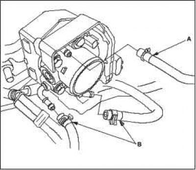
4. Remove the hose A of the canister of the fuel vapor absorber (EVAP) and coolant bypass hoses B.
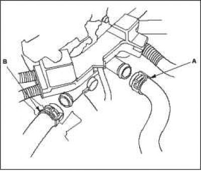
5. Remove the upper radiator hose A and the lower radiator hose B.
 |  |
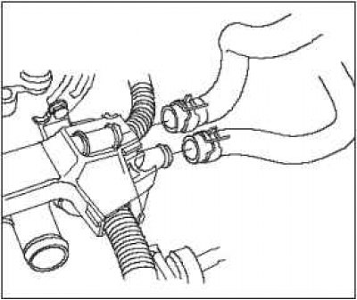
6. Remove the heating system hoses.
7. Remove the drive belt.
8. Remove the intake manifold.
9. Remove the exhaust manifold.
10. Remove the engine harness connectors and harness retainers from the head.
- Four fuel injector connectors.
- Socket of the sensor of 1 temperature of a cooling liquid (EATING).
- Camshaft position sensor connector (CMP).
- Oil pressure sensor connector.
- knock sensor connector.
- EGR Valve Connector (EGR).
11. Remove the fuel distribution rail.
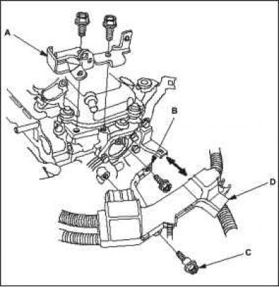
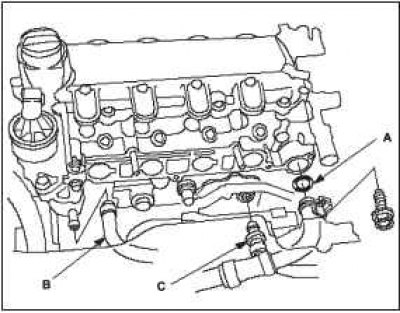
12. Remove the bracket for fastening the air cleaner housing A, wire «masses» B and wire harness retainer mounting bolt C, then remove the wire harness retainer from its bracket.
13. Remove connecting hose A, coolant bypass hose B, hose C of the positive crankcase ventilation system (PCV).
14. Remove the cylinder head cover.
 |  |
15. Set piston #1 to top dead center (TDC). Label «UP» on the camshaft sprocket should be on top, and the top dead center marks (TDC) on the sprocket must align with the top edge of the cylinder head.
16. Turn out a fixing bolt of an arm of the generator and weaken a fixing bolt of the generator.
17. Remove the bypass roller.
18. Remove the water pump pulley.
 |  |
19. Remove the crankshaft pulley.
20. Disconnect the crankshaft position sensor connector (CKP), then remove the wire harness clips.
21. Support the engine with a 300x300x25mm wood beam and a jack under the oil pan.
Note. Do not install a jack under the center of the oil pan to avoid damaging it.
22. Remove the connection cable from «weight», then remove the top bracket.
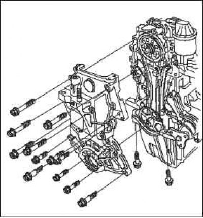
23. Avoid contact between the alternator and the timing chain case. Remove the timing chain case.
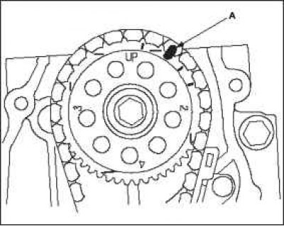
24. Mark A on the drive chain sprocket and on the timing chain.
25. Reinstall, without tightening, the crankshaft pulley.
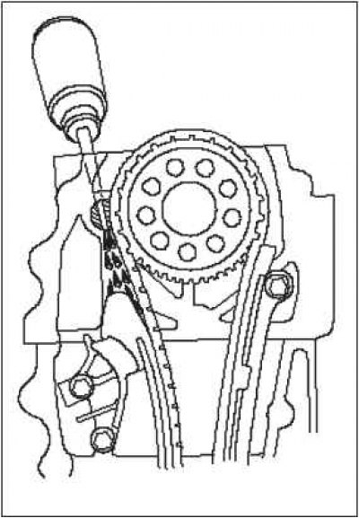
26. Lubricate the sliding surface of the timing chain tensioner slider through the oil return hole in the cylinder head with engine oil.
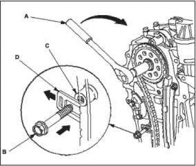
27. While holding the crankshaft pulley, install socket A on the camshaft sprocket bolt.
28. Turn the camshaft counterclockwise to compress the timing chain tensioner, then install the 6x1.0mm bolt B into hole C on the engine block through the timing chain tensioner.
Note. The torque must exceed 44 Nm when turning the camshaft.
Do not turn the camshaft counterclockwise.
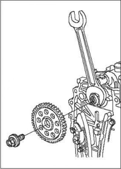
29. While holding the camshaft with an open-end wrench, remove the camshaft sprocket.
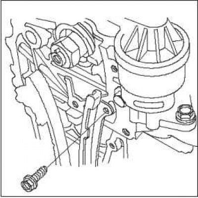
30. Remove the timing chain guide mounting bolt.
 |  |
 |  |
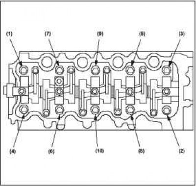
31. Remove the cylinder head cover bolts. To avoid warping, loosen the bolts 1/3 turn each in sequence and repeat these steps until all bolts are loose.
32. Remove the cylinder head.