
Note: Cover the fenders to prevent damage to the paintwork.
To avoid damaging wires and terminals, disconnect electrical connectors carefully, holding the connector by its body.
Label all wire harnesses and hoses to avoid confusion during installation. Also make sure they do not touch other wires or hoses or come into contact with other parts.
1. Make sure you know the anti-theft code for the audio system and navigation system, save the custom settings for the audio system.
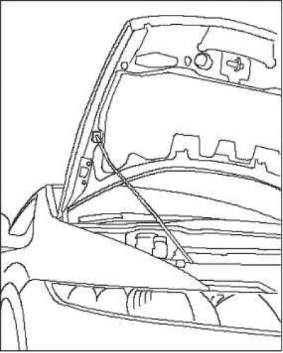
2. Lock the hood in the fully open position (the retaining post must be installed in the lower hole).
3. Relieve the fuel pressure.
4. Disconnect the negative cable from the battery, then disconnect the positive cable.
5. Remove the battery.
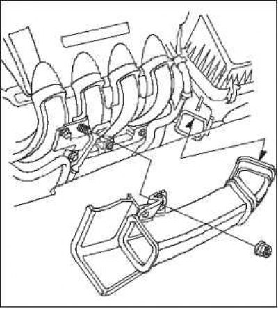
6. Remove the intake pipe.
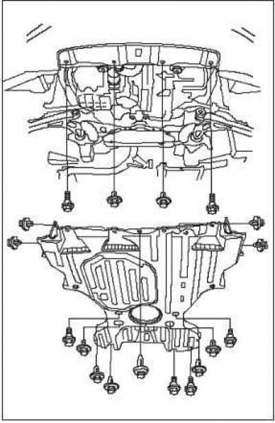
7. Remove the panel under the shield.
8. Remove the air cleaner housing assembly.
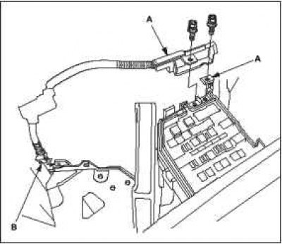
9. Disconnect the battery cables A from the fuse/relay box.
10. Remove the harness clamp B.
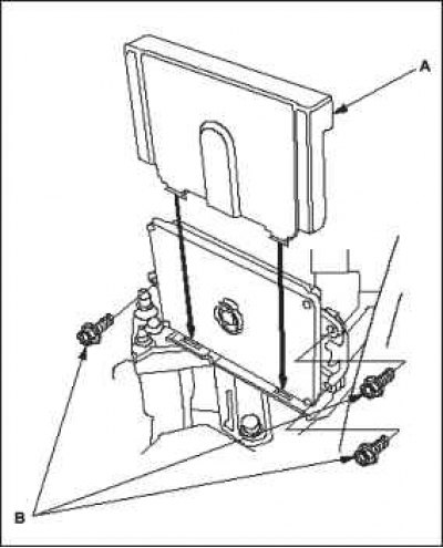
11. Remove the engine control module (ECM) cover A, then remove the three ECM mounting bolts B.
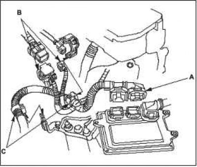
12. Disconnect ECM connectors A and engine wire harness connectors B.
13. Remove the wiring harness retainer C.
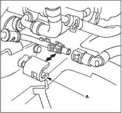
14. Remove the quick release cap A, then disconnect the fuel supply hose.
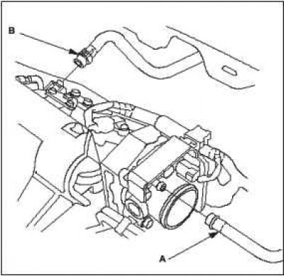
15. Remove the Fuel Vapor Absorber tank (EVAP) hose A and the brake booster vacuum hose B.
 |
 |
16. Remove the steering wheel.
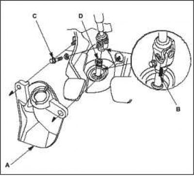
17. Remove the steering joint cover A.
18. Apply a mark B across the steering joint and the steering gear pinion shaft. Remove the steering shaft joint bolt C and disconnect the joint from the steering gear pinion shaft D.
19. Remove the gear shift cable.
 |
 |
20. Remove the clutch slave cylinder and the mounting bolt of the bracket holding the clutch hydraulic drive pipe.
21. Remove the drive belt.
22. Remove the radiator cap.
23. Raise the machine to the full height of the lift.
24. Remove the front wheels.
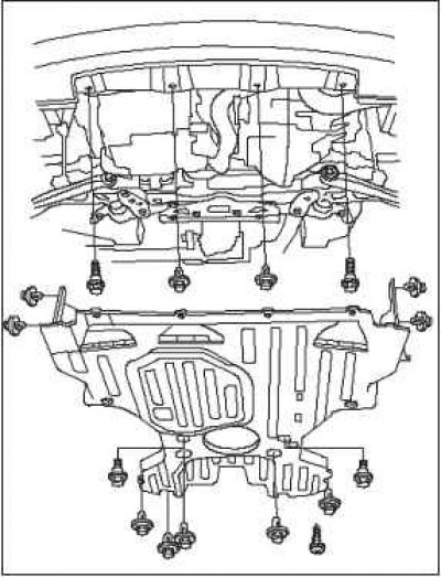
25. Remove the lower engine cover.
26. Loosen the drain plug on the radiator and drain the coolant.
27. Drain the engine oil.
28. Drain the transmission oil
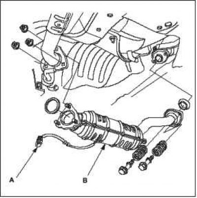
29. Disconnect the secondary heated oxygen sensor connector (secondary HO2S) A, then remove the three-way catalytic converter B.
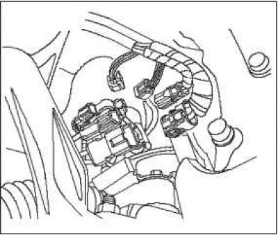
30. Disconnect the connectors from the steering gear.
31. Separate the anti-roll bar links from the shock absorbers.
32. Separate the ball joints at the end of the steering rod from the cams.
33. Disconnect the hinges from the lower arms.
34. Remove the drive shafts. Lubricate all precision machined surfaces with engine oil. Place plastic protective boots on the ends of the drive shafts.
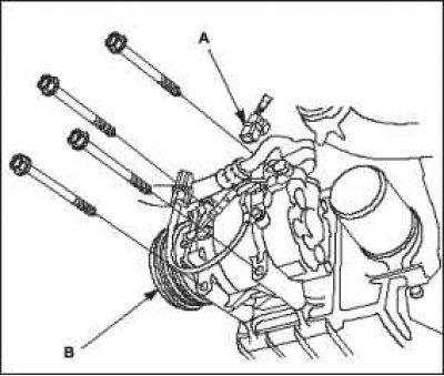
35. Disconnect the A/C compressor clutch connector A, then remove the A/C compressor B without disconnecting the A/C hoses (with air conditioning).
36. Lower the car on the lift.
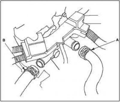
37. Remove the upper radiator hose A and the lower radiator hose B.
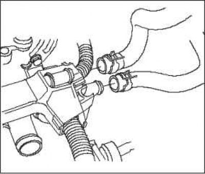
38. Remove the heating system hoses.
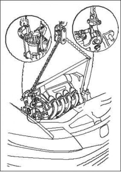
39. Attach the chain hoist to the engine as shown in the figure.
40. Make sure the lift mounts are positioned correctly. Raise the lift to its maximum height.
41. Remove the lower reaction rod.
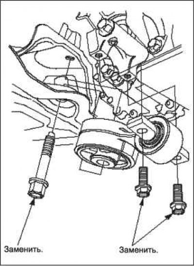
42. Remove the subframe.
43. Make sure the lift mounts are positioned correctly. Lower the vehicle onto the lift.
44. Unscrew the nuts of the side engine support mounting bracket.
45. Remove bolt and nuts A from the transmission mounting bracket.
46. Remove the ground connection cable B.
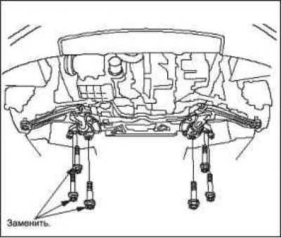 |
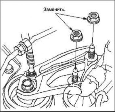 |
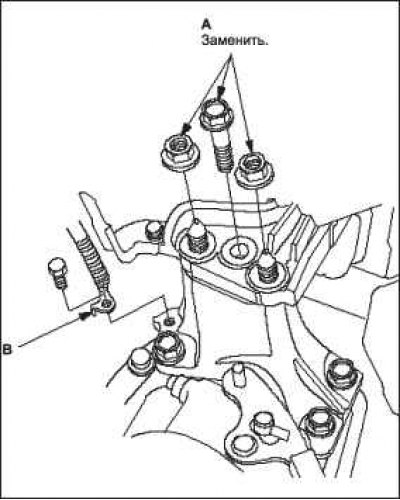
47. Make sure all vacuum hoses, fuel and coolant lines, and electrical wires are disconnected from the engine and transmission.
48. Gradually lower the engine/gearbox unit by 150 mm. Once again, ensure that all hoses and electrical wires are disconnected and not caught on the engine/gearbox, then lower the engine/gearbox completely.
49. Disconnect the chain hoist from the engine/gearbox block.
50. Raise the vehicle completely and remove the engine/transmission assembly from under the vehicle.
(Original published on this resource: hondabook)