
2. Check the battery charge level - the accuracy of controlling the composition of the air-fuel mixture largely depends on the proper functioning of the PCM and information sensors, which is determined, among other things, by the level of their supply voltage.
3. Check the condition of the air cleaner filter element - even a partial blockage of the air filter has a significant impact on fuel economy and engine output (see chapter Current service).
4. Check the proper functioning of the fuel pump (see Check of serviceability of functioning of the fuel pump/fuel pressure). If the pump fuse is blown, replace it with a new one. If the new fuse also fails immediately, check the circuit wiring for signs of short circuits (see chapter Onboard electrical equipment).
5. Check up a condition of the vacuum hoses connected to the inlet pipeline.
6. Disconnect the air hose from the throttle body and check the latter for carbon deposits and other contaminants (especially in areas close to the throttle valve). In case of detection of signs of contamination of the throttle body, refer to the materials of the Chapter Engine management systems and troubleshoot the PCV and EGR systems. In case of severe contamination, the throttle body must be replaced.
Attention! The throttle chamber walls, throttle valve and its axis on the considered models of vehicles are covered with a protective film, which should not be attempted to be removed in order to avoid accidental damage to components.
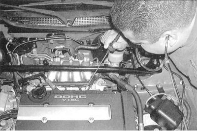
7. With the engine running, listen in turn with a stethoscope to each of the injection injectors - a uniform click indicates that the injector is functioning properly (see accompanying illustration). In the absence of a stethoscope at hand, use a long screwdriver, simply pressing the tip of its tip against the injector body and focusing on the vibrations transmitted through the handle.
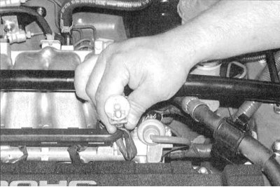
8. When detecting malfunctions of the injector, you should use a special probe lamp for diagnosing injectors (ask at car accessories stores) - the lamp is connected to the electrical connector of the suspected injector (see accompanying illustration). Start the engine and check all injectors with a lamp. Uniform flashing of the lamp confirms the correct functioning of the injector.
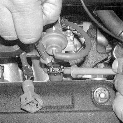
9. Stop the engine, disconnect the electrical connectors of the injectors and measure the electrical resistance of each of them (see accompanying illustration). Compare measurement results with requirements Specifications. If necessary, replace the failed node.
10. Additional information on the diagnosis of the condition of the injection system is contained in Chapter Engine management systems.