
Examination
1. The need to adjust the valve clearances arises only after the replacement or repair of the components of the valve mechanism.
2. The easiest way to check the valves is to listen to the engine with the hood open. The need for adjustment is indicated by an increased background noise emitted by the valve mechanism.
Adjustment
Valve clearances are checked and adjusted with a cold engine.
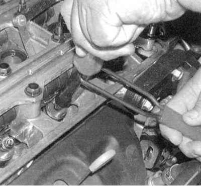
1. Remove the cylinder head cover (see the relevant Part of the Chapter Engine).
2. After turning the crankshaft, bring the piston of the first cylinder to the TDC position of the end of the compression stroke (see chapter Engine). The shaft turns in the direction of normal rotation (clockwise) until the TDC mark on its pulley is aligned with the pointer on the lower cover of the timing belt, and the UP mark on the gear (Oh) camshaft (ov) will not be in the 12 o'clock position.
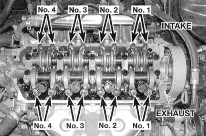
3. Having brought the engine to this position, you can begin to check and adjust the valves of the first cylinder (see accompanying illustration).
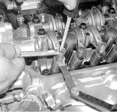
4a. Start with the intake valve. Thread the probe blade to the required thickness (see Specifications) into the gap between the end of the valve stem and the rocker arm of the valve drive (Civic models), or by the working protrusion of the corresponding intake camshaft cam and the valve drive lever (Integra models) (see accompanying illustrations).
4b. The feeler gauge should slide through the gap with little resistance. If necessary, loosen the locknut and loosen the adjusting screw, then begin to tighten the screw until you get the desired effect on the stylus blade.
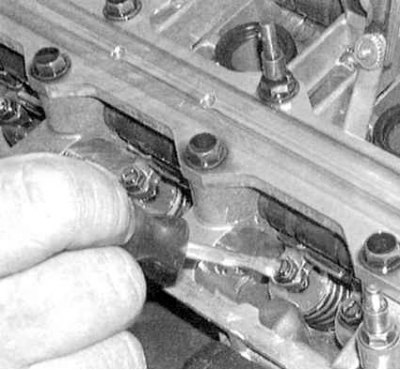
5. Having fixed the adjusting screw from turning with a screwdriver, tighten the lock nut (see accompanying illustration). Make sure that the gap does not change during the tightening of the nut, then, proceeding in a similar manner, alternately adjust the gaps of the second inlet valve and the two exhaust valves. 6. Turning the crankshaft 180°counterclockwise (the camshaft pulley must rotate 90°), bring the piston of the third cylinder to the TDC position of the end of the compression stroke. In this case, the UP mark on the gear (Oh) camshaft (ov) should move to the 9 o'clock position. Check and adjust the valves of the third cylinder.
7. Rotate the crankshaft another 180°counterclockwise (label (And) UP will go down at 6 o'clock) and adjust the valves of the fourth cylinder.
8. Once again turning the crankshaft 180° (label (And) UP should move to the 3 o'clock position). And repeat the procedure for the valves of the second cylinder.
9. When you have finished adjusting the valves, reinstall the cylinder head cover (see the relevant Part of the Chapter Engine).