
Note: Valve adjustment should only be performed when the cylinder head temperature is below 38°C.
1. Remove the cover from the cylinder head.
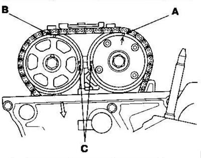
2. Set the piston of cylinder No. 1 to TDC. The stamped mark (A), marked with an arrow on the electronic variable valve timing (VTC) actuator, and the mark (B) on the exhaust camshaft sprocket must be on top. Align the TDC (C) marks on the VTC actuator and the exhaust camshaft sprocket.
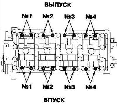
3. Select a feeler gauge of the required thickness for the valves you are going to check.
Inlet: 0.21-0.25 mm
Issue: 0.28-0.32 mm
Location of adjustment screws
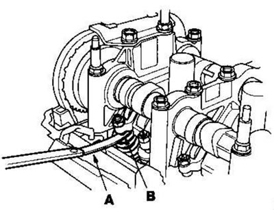
4. Insert the feeler gauge (A) between the adjusting screw (B) and the end of the valve stem and move it back and forth; You should feel some resistance.
5. If the resistance is too high or too low, loosen the lock nut (A) and turn the adjusting screw (B) until the desired resistance is achieved on the feeler gauge.
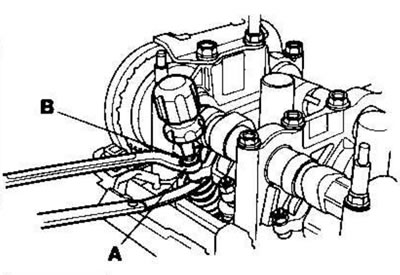
Intake: 20 Nm (2.0 kgf·m)
Release: 14 Nm (1.4 kgf·m)
6. Tighten the lock nut and check the clearance again. Repeat adjustment if necessary.
7. Turn the crankshaft 180° clockwise (the camshaft pulley turns 90°).
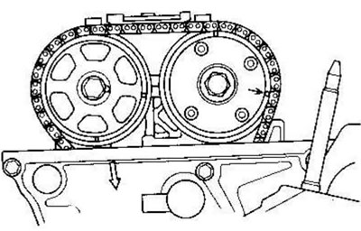
8. Check and, if necessary, adjust the valve clearance on cylinder No. 3.
9. Turn the crankshaft 180° clockwise (the camshaft pulley turns 90°).
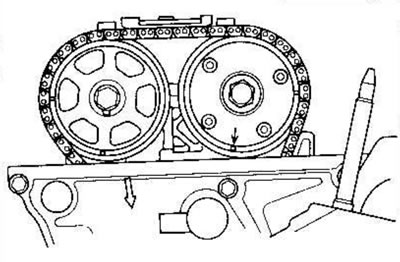
10. Check and, if necessary, adjust the valve clearance on cylinder No. 4.
11. Turn the crankshaft 180° clockwise (the camshaft pulley turns 90°).
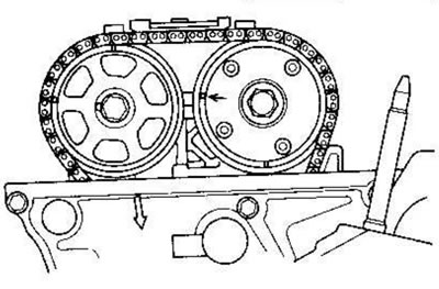
12. Check and, if necessary, adjust the valve clearance on cylinder No. 2.
13. Install the cover on the cylinder head.