
Contents: Examination ⇊ Adjustment ⇊
Examination
The need to adjust valve clearances arises only after replacing or repairing valve mechanism components.
The simplest way to check the valves is to listen to the engine with the hood open. The need for adjustment is indicated by increased noise levels emitted by the valve mechanism.
Checking and adjusting valve clearances should be done with the engine cold.
Adjustment
4-cylinder engines
1. Remove the cylinder head cover and the upper timing belt cover (see Chapter Engine).
2. Bring the piston of the first cylinder to the TDC position at the end of the compression stroke, for which you should turn the crankshaft by the pulley so that the "UP" mark on the camshaft gear is in the 12 o'clock position (see Chapter Engine).
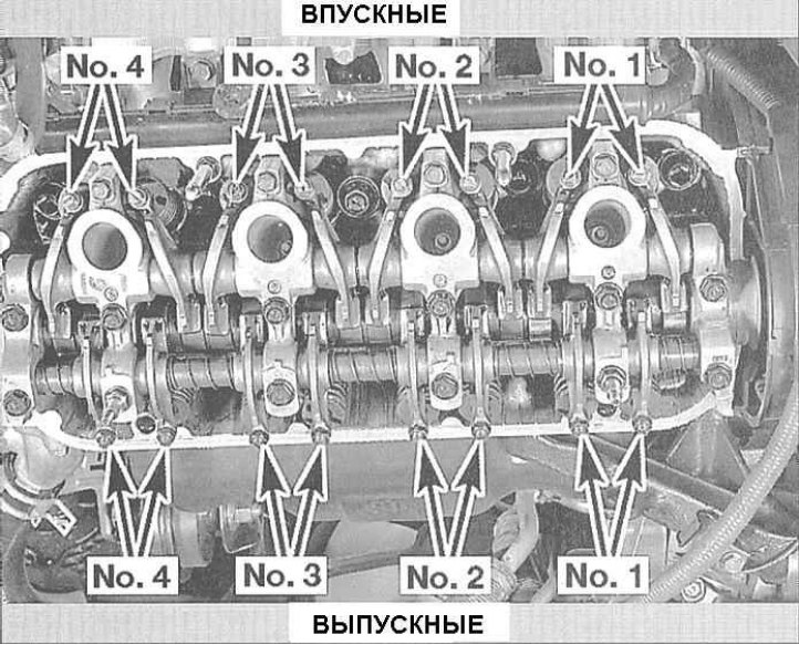
3. Having brought the engine to the specified position, you can begin checking and adjusting the valves of the first cylinder. The diagram of the valve arrangement on the engine is shown in the illustration.
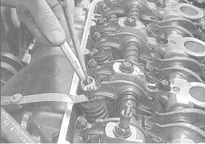
4. Start with the intake valve. Insert the blade of a feeler gauge of the required thickness (see Specifications) into the gap between the end of the valve stem and the rocker arm of its valve drive. The feeler gauge should slide in the gap with slight resistance. If necessary, loosen the lock nut with a spanner, loosen the adjusting screw with a screwdriver, then begin to tighten it, achieving the desired effect on the blade of the feeler gauge.
5. Using a screwdriver to prevent the adjusting screw from turning, tighten the lock nut. Make sure that the clearance has not changed while tightening the nut, then, acting in a similar manner, adjust the clearances of the second intake valve and the two exhaust valves one by one.
6. Turn the crankshaft 180° counterclockwise (the camshaft gear should turn 90°), bring the piston of the third cylinder to the TDC position of the end of the compression stroke. In this case, the UP mark on the camshaft gear should move to the 9 o'clock position. Check and adjust the valves of the third cylinder.
7. Turn the crankshaft another 180° counterclockwise (the UP mark will move down to 6 o'clock) and adjust the valves of the fourth cylinder.
8. Once again, turn the crankshaft 180° (the UP mark should move to the 3 o'clock position), and repeat the procedure for the valves of the second cylinder.
9. After completing the valve adjustment, reinstall the cylinder head and timing belt covers.
V6 engines
1. Remove the upper intake manifold plenum, the upper front cylinder bank timing belt cover, and both cylinder head covers (see Chapter Engine).
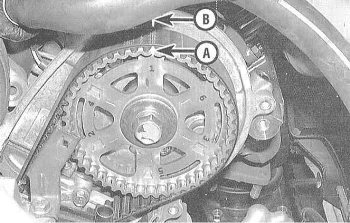
2. Turn the crankshaft and bring the piston of the first cylinder to the TDC position (see Chapter Engine). In this case, the corresponding mark on the camshaft gear must be aligned with the indicator on the rear cover of the timing drive.
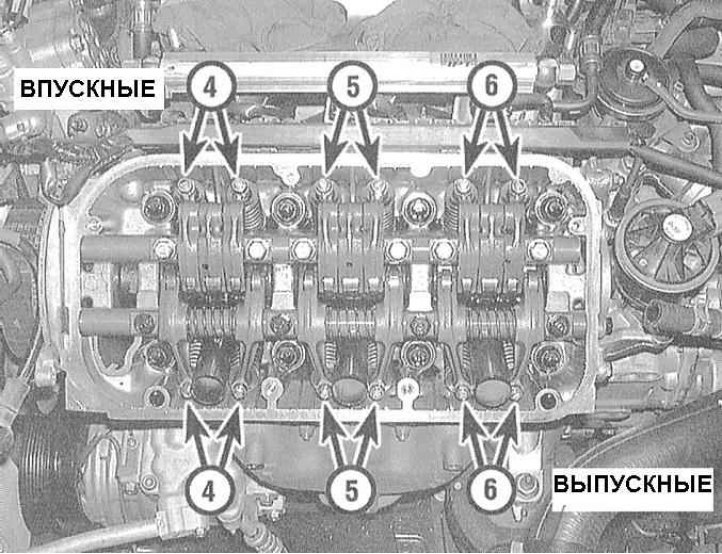
3. In the specified position of the engine, adjust the valves of the first cylinder.
Note: Each cylinder has 4 valves (2 intake and 2 exhaust). The procedure is the same as described above in paragraphs 3 and 4 of this Section.
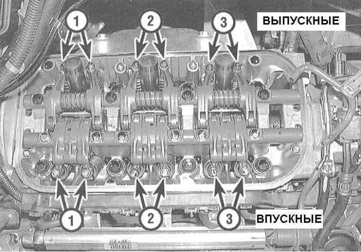
4. Turn the crankshaft by the pulley clockwise, align the TDC mark of the 4th cylinder with the indicator and adjust its valves. Continuing to act in a similar manner (go cylinder by cylinder in the order of ignition), adjust the valves of all the remaining cylinders one by one.
Note: The crankshaft should be turned clockwise each time.
5. Reinstall the cylinder head covers, upper timing belt cover and upper intake manifold plenum.