
Contents: Tempostat activation switch ⇊ Rear window defroster activation…⇊ Instrument panel and running lights…⇊
Warning! The vehicles covered in this manual are equipped with airbags (SRS). When performing any work near the impact sensors, steering column or instrument panel, turn off the SRS (see Airbags - General Information). Do not test SRS models with any type of diagnostic equipment.
Tempostat activation switch
Examination
1. To check, the switch must be removed from the vehicle (see paragraph 1, Replacement).
2. Using a test lamp or one equipped with an individual power source, check for conductivity between the switch terminals in both its positions (see table below). Replace the switch if necessary.
Tempostat Activation Switch State Map
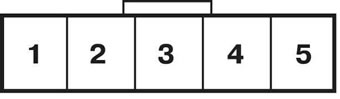 | 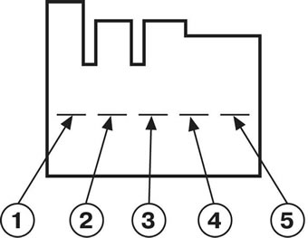 |
| Switch position | Presence of conductivity between the terminals |
| ON(ON) | |
| Civic | 2 and 3 |
| Integra | 1 and 2 |
| Off (OFF) (lamp check) | |
| Civic | 1 and 2; 4 and 5 |
| Integra | 2 and 3; 4 and 5 |
Replacement
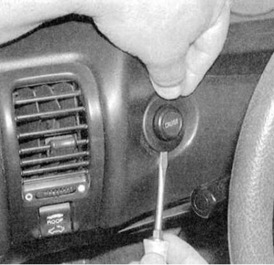
1. Pry the switch with a small screwdriver and remove it from the instrument panel (see accompanying illustration). Disconnect the electrical connector.
2. Installation is carried out in reverse order.
Rear window defroster activation switch
Examination
1. Remove the switch from the instrument panel (see below paragraph 1, Replacement).
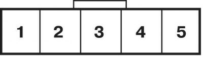
2. On Civic models, a timer is included in the switch circuit, which requires a special method of testing. In case of malfunction of the heater, turn on the ignition (do not start the engine), then connect the positive probe of the voltmeter to terminal #1 of the switch wiring harness connector, and connect the negative probe to terminal #4 (see accompanying illustration). The device should register battery voltage, otherwise check the condition of the wiring and circuit fuse.
3. If battery voltage is present, install a jumper wire between terminals #1 and #4. If the heater now operates, replace the switch, otherwise check the condition of the heater relay (see Relay - general information and checking the correct functioning) with the corresponding chain.
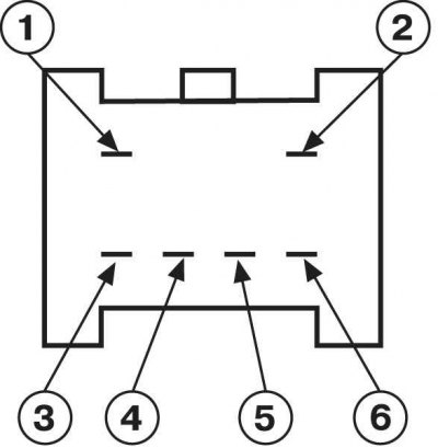
4. On Integra models, use an ohmmeter or a test lamp equipped with an individual power source to check for continuity between the switch terminals (see accompanying illustration and table below). If the test results are negative, replace the switch.
Rear Window Defogger Activation Switch Status Map (integra models)
| Switch position | Presence of conductivity between the terminals |
| ON(ON) | 4 and 6 |
| Off (OFF) (lamp check) | 1 and 3; 2 and 5 |
Replacement
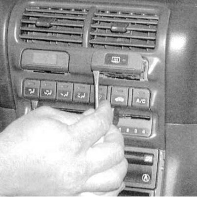
1. Using a screwdriver, carefully remove the switch from the vehicle's instrument panel (see accompanying illustration). Disconnect the electrical connector.
2. Installation is carried out in reverse order.
Instrument panel and running lights switch
Examination
1. Remove the switch from the vehicle's instrument panel (see below paragraph 1, Replacement).
2. The circuit breaker includes a control circuit, so the check is performed using a special method. During the check, each circuit is tested individually. If the system is not functioning properly, but no faults are found in the circuits, then the circuit breaker is most likely damaged. Check the condition of the circuit breaker terminals. If necessary, clean oxidized terminals, straighten deformed ones. If necessary, replace the circuit breaker.
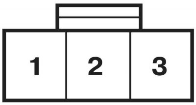
3. Connect an ohmmeter between terminal #2 of the switch wiring harness connector and chassis ground (see accompanying illustration). There should be continuity, otherwise check the circuit for an open circuit and the tightness of the terminal connections.
4. With the headlights on, connect a voltmeter between terminal #1 and ground. If there is no battery voltage, check the condition of the circuit components to the under-dash mounting block and to the combination switch.
5. With the headlights on, install a jumper wire between terminal #3 and chassis ground. The instrument panel lighting should turn on at maximum brightness.
6. If the connecting wiring is OK, replace the switch.
Replacement
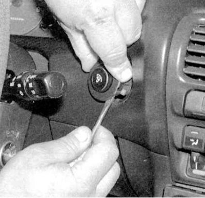
1. Using a screwdriver, carefully pry the switch out of the vehicle's instrument panel (see accompanying illustration). Disconnect the electrical connector.
2. Installation is carried out in reverse order.