
Attention! The vehicles covered in this manual are equipped with airbags (SRS). When performing any work near the shock sensors, steering column or instrument panel, turn off the SRS (see Airbags - general information). Do not test SRS models with any type of diagnostic equipment.
Ignition switch
1. Disconnect from the battery at first a negative wire, then positive.
Attention! If the stereo system installed in the car is equipped with a security code, before disconnecting the battery, make sure that you have the correct combination to activate the audio system!
2. Remove the lower section of the instrument panel and steering column covers (see chapter Body).
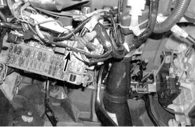
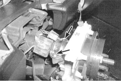
3. Moving along the switch wiring harness down along the steering column to the mounting block, disconnect the electrical connectors (see accompanying illustrations).
4. Check for continuity between the switch terminals (see table below).
5. If there are irregularities in the conductance distribution, replace the switch.
6. Insert the key into the lock and turn it to the LOCK position (blocking).
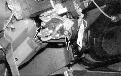
7. Turn out two fixing screws and remove the switch from a steering column (see accompanying illustration).
8. Installation is carried out in the reverse order.
Ignition Switch Status Map
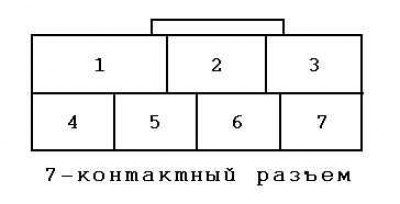 | 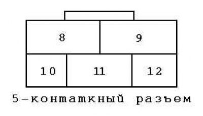 |
| Switch position | Conductivity between terminals |
parking position (ACC) | |
Civic | 3 and 8 |
Integra | 3 and 11 |
On (ON) | |
Civic | 3, 8, 10 and 12 |
Integra | 3, 8, 9 and 11 |
launch (START) | |
Civic | 1, 3 and 12 |
Integra | 1, 3 and 8 |
Cylinder and Steering Lock Assembly
1. Turning the cylinder in all of the positions provided, evaluate the degree of wear by the amount of play. The position of the key in the lock must correspond to the marking on the body of the assembly. In the event of a cylinder failure, the entire lock assembly must be replaced.
2. Disconnect from the battery at first a negative wire, then positive.
Attention! If the stereo system installed in the car is equipped with a security code, before disconnecting the battery, make sure that you have the correct combination to activate the audio system!
3. Remove the steering column cover and the lower section of the instrument panel (see chapter Body).
4. Remove the ignition switch (see above).
5. Give fixing nuts and lower a steering column.
6. The lock assembly is fixed in the column with a yoke tightened with two shear head screws (see accompanying illustration). Point the screw heads, then drill them out (use a 4.8 mm drill). Remove the clamp and remove the lock assembly from the steering column.
7. Without inserting the key, install the replacement lock in its original place and secure it with bolts and nuts. Tighten the nuts securing the steering column to the instrument panel flange with a force of 12.2 Nm. The tie bolts of the mounting sleeve are tightened to 22 Nm.
8. Reinstall the ignition switch and the instrument panel and steering column shroud sections.
9. Connect to the battery at first a positive wire, then negative.