
Contents: Main Tempostat Activation Switch ⇊ Hazard warning switch ⇊ Rear window defroster activation…⇊
Warning! The models of vehicles covered in this manual are equipped with a supplemental restraint system (SRS). Before performing any work near the air bag unit, steering column or instrument panel, turn off the SRS to avoid injury from accidental deployment (see Section Airbags - General Information). The SRS circuit wiring is easily identified by the yellow color of the insulation.
Main Tempostat Activation Switch
Examination
1. To check, the switch must be removed from the vehicle.
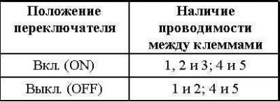
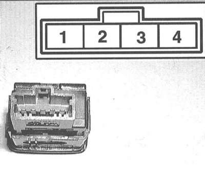
2. Using a test lamp or one equipped with an individual power source, check for continuity between the switch terminals in both positions. Replace the assembly if necessary.
Replacement
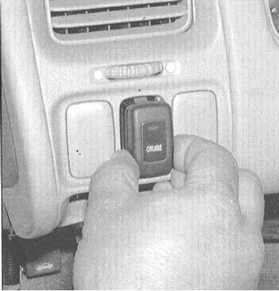
1. Pry the switch with a small screwdriver and remove it from the instrument panel. Disconnect the electrical connector.
Note: To avoid damaging the plastic, place a strip of tape on the tip of the screwdriver.
2. Disconnect the wiring and remove the switch assembly.
3. Installation is carried out in reverse order.
Hazard warning switch
Examination
1. To check, release the switch from the panel clock assembly trim.
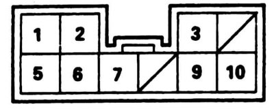
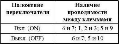
2. Make sure that the conductivity is distributed correctly between the terminals in both switch positions. Replace the assembly if necessary.
Replacement
1. Carefully pry up and remove the panel clock assembly with its casing from the center section of the instrument panel.
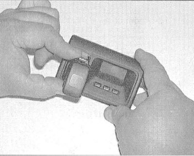
2. Disconnect the 10-pin connector from the back of the switch. Press the locking tab and release the switch assembly from the clock faceplate.
Rear window defroster activation switch
Examination
1. The switch is part of the heater/air conditioner control panel assembly. The assembly removal and installation procedures are described in Chapter Cooling and heating systems.
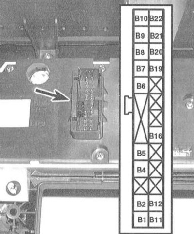
2. Using an ohmmeter or a test lamp equipped with an independent power source, check for continuity between terminals B4 and B9 of the 22-pin control panel connector. Continuity should only occur when the heating and glass are turned on (the switch button is recessed). Replace the switch if necessary.
Replacement
1. Remove the screws that secure the front and rear sections of the control panel together. Keep the front panel facing up while removing it.
Note: Before disassembling the control panel, prepare a replacement switch, which may need to be ordered from a company service station.
2. Remove the old switch and install the new one in its place, then press the front and rear sections of the heater/air conditioner control panel together and press them together by hand. Install and tighten the mounting screws.
3. Install the control panel assembly in its original place (see Chapter Cooling and heating systems).
The article is based on information from the website HONDABOOK