
Contents: General information ⇊ Operating principle ⇊ SRS self-diagnosis system ⇊ Servicing of components located near…⇊ Disabling the SRS system ⇊ Activation of the SRS system ⇊ Removal and installation of airbag…⇊
General information
All models covered in this Guide are equipped with a Supplemental Restraint System (SRS), better known as airbags. Two airbags are included as standard equipment. The system provides additional protection for the driver and front passenger of the vehicle in the event of a severe frontal impact.
The system consists of an SRS unit with a directional overload sensor, a control sensor, a self-diagnosis circuit and a feedback circuit. The unit is located under the instrument panel, directly in front of the central console. The airbag modules are mounted in the central part of the steering wheel and the right part of the vehicle's instrument panel (directly above the glove compartment).
Operating principle
A necessary condition for the activation of the airbags is the activation of the directional overload sensor and the control sensor. The activation of the sensors leads to the closure of the module circuit and the immediate filling of the airbags with gas. In the event of a battery failure, the airbags are activated by the energy generated by the feedback unit built into the SRS unit.
SRS self-diagnosis system
The SRS self-diagnosis system turns on the indicator lamp on the vehicle's instrument panel when the ignition key is turned to the ON position. If the system does not detect any abnormalities, the lamp should go out after approximately 6 seconds. If the indicator lamp does not turn off, or the lamp comes on while the vehicle is moving, then a malfunction has been detected in the SRS system. The vehicle should be taken to a service station to have the system checked and the cause of the malfunction eliminated.
Servicing of components located near SRS components
If it is necessary to remove the steering wheel or service the radio or other components located near the instrument panel, be careful not to disconnect the electrical connectors of the SRS circuit. Never connect any diagnostic equipment to the SRS circuit. WHEN SERVICING ANY COMPONENTS NEAR THE AIR BAG, ALWAYS DISABLE THE SRS FIRST (see below).
Disabling the SRS system
Caution! The SRS system must be deactivated each time servicing procedures are performed on components located near the airbags!
1. Disconnect the negative cable from the battery first, then the positive cable.
Warning! If the car stereo system is equipped with a security code, make sure you have the correct combination to activate the audio system before disconnecting the battery!
2. Connect the jumper plugs (red color) to the airbag connectors (see below).
Driver's airbag
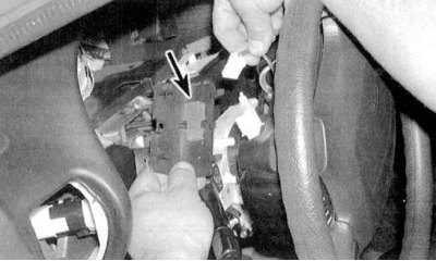
1. Remove the access cover located underneath the airbag module, then remove the red jumper plug (see accompanying illustration).
2. Disconnect the 2-pin connector installed between the air bag module and the cable drum.
3. Insert the jumper plug into the 3-pin connector on the airbag side.
Passenger airbag
1. Remove the glove box (see Chapter Body).
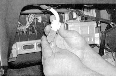
2. Disconnect the electrical connector located between the passenger air bag module and the SRS main wiring harness. Insert a jumper plug into the connector on the air bag side (see accompanying illustration).
Activation of the SRS system
1. To activate the SRS system after it has been deactivated (for the purpose of performing maintenance procedures on any components), remove the red jumper plugs from the connectors, then restore the original wiring connections (to the cable drum and SRS main harness)install the jumper plugs into their holders and replace the access cover/glove compartment.
2. Turn off the ignition.
3. Connect the battery (first the positive wire, then the negative).
Removal and installation of airbag modules
1. Disable the SRS system (see above).
2. The procedure for removing the driver's airbag module is described in Chapter Suspension and steering.
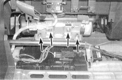
3. To remove the passenger airbag, remove the two mounting screws (see accompanying illustration).
4. Installation is performed in reverse order. Do not forget to activate the system (see above).
[Full version on the source website: hondabook.ru]