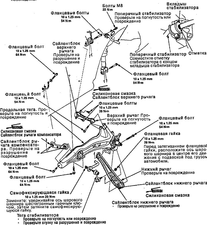
Replacing suspension arms
Attention.
- Replace self-locking nuts after removal.
- The vehicle should be lowered to the ground before tightening the bolts and nuts associated with the rubber mounts and bushings.
Note:
- Make sure the toe angle adjustment bolts on the compensator arm are set in the same direction.
- "t UP L" or "t UP LH G" or "t UP LK" or "t UP LS" written on the upper left arm and "t UP R" or "t UP RH G" or "t UP RKM" or "t UP RS" on the upper right arm.
- The right and left compensators are symmetrical. Set with a check mark "UP*1 forward.
- After installing the suspension arm, check the wheel alignment and adjust if necessary.
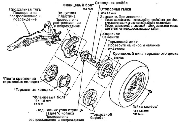
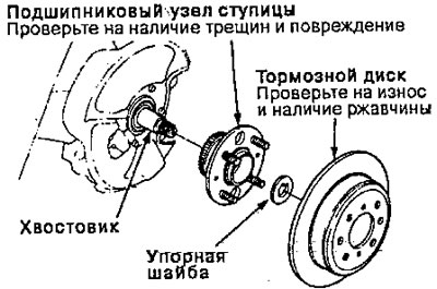
Replacing the Wheel Bearing Assembly
Note:
- Use only original wheel weights for aluminum wheels. Non-original weights can cause corrosion and damage to aluminum wheels.
- On aluminum wheels, remove the center cap from the inside of the wheel after removing the wheel.
- Before installing the brake disc, clean the mating surface of the rear hub and brake disc (or brake drum) *
- Before installing the wheel, clean the mating surface of the brake disc (or brake drum) and wheels*
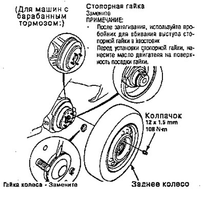
- For vehicles with drum brakes.
1. Slightly loosen the wheel nuts.
2. Raise the rear of the machine and secure it on safe stands in appropriate locations*
3. Remove the wheel nuts and rear wheel.
4. Pull up the parking brake lever.
5. Remove the cap.
6. Lift the locking tab on the lock nut, then remove the nut.
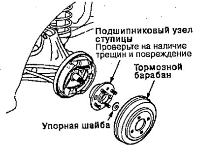
Note: Be careful» to avoid damaging the hub assembly when disassembling the hub assembly bearing.
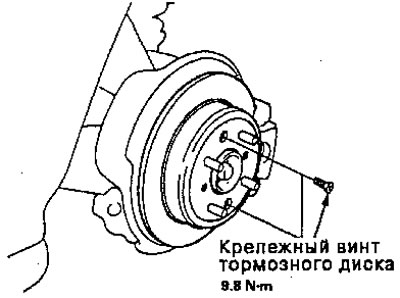
7. Remove the M6 mounting screws of the brake disc
8. Release the parking brake lever.
9. Remove the brake drum, hub assembly bearing and lock washer (for vehicles with drum brake).
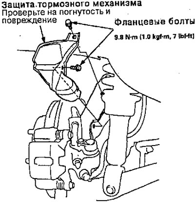
10. Remove the MB flange bolts and brake protection.
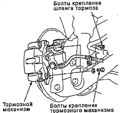
11. Remove the two brake hose bolts.
12. Remove the brake pad bracket bolts and hang the brake caliper on one side.
Attention. To prevent accidental damage to the brake mechanism or brake hose, use a short piece of wire to suspend the caliper from the chassis.
13. Screw two M8 x 1.25 bolts into the disc to push it out of the hub.
Note: Screw in each bolt two turns in increments to prevent excessive kinking of the disc.
14. Remove the brake disc.
15. Remove the hub bearing assembly from the shank.
16. Install in the reverse order of removal.
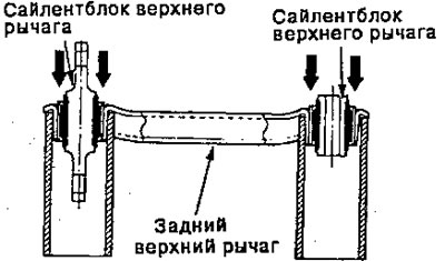
Replacing the silent block of the upper arm
1. Remove the upper control arm bushings as shown
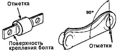
2. Draw a marking line on the silent block of the upper arm like this. so that it is in line with the bolt mounting plane.
3. Mark two points on the upper arm so that they are in line and at the correct angle as shown in the drawing.
4. Insert the silent block of the upper arm with the marks aligned.
5. Insert the upper arm bushing into the upper arm.
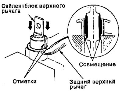
Note: Insert the upper arm bushings flush with the upper arm.
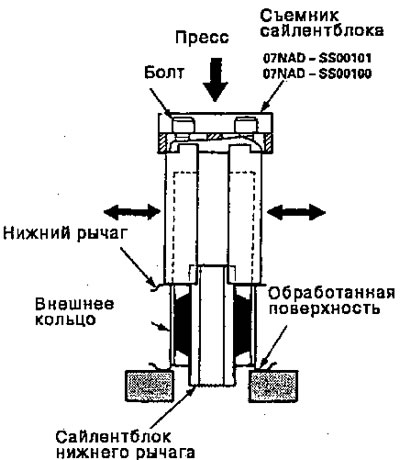
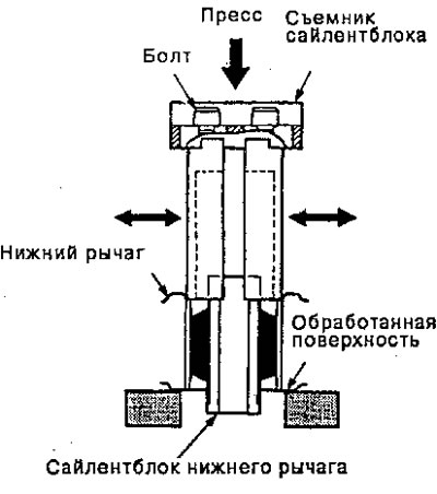
Replacing the lower arm silent block
1. Place the lower arm on the press, machined surface down.
2. Adjust to fit the inside diameter of the hole, then tighten the bolts securely.
3. Place the puller on the silent block.
4. Remove the silent block by pressing the puller with a press as shown.
Attention.
- Secure the lower arm into the machined surface as shown.
- Be careful not to damage the inside of the lever hole when pushing out the bushing.
5. Adjust the silent block puller so that it fits the outer diameter of the hole.
6. Place the silent block remover on the outer ring of the silent block.
7. Press the bushing into the lower arm using a puller and a press until the edges of the bushing are aligned with the machined surface on the lower arm as shown.