
- After removal, replace the self-locking nuts.
- The vehicle must be lowered to the ground before tightening the bolts or nuts on the rubber mounts or bushings.
- After installing the suspension arm, check the rear wheel alignment angles (see above).
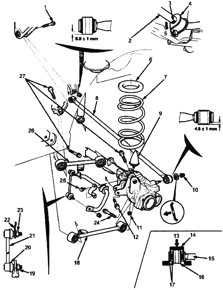
1. BOLT WITH SHELL, 10x1.25 mm, 54 Nm (5.5 kgf/m)
2. STABILIZER ROD. Align the stabilizer mark with the end of the stabilizer bushing.
3. BOTTOM
4. STABILIZER BUSHING
5. LABEL
6. UPPER SPRING SEAT. Check for wear and damage.
7. SPRING. Check for weakening of compression and damage.
8. PANHARD. Check for bending and damage.
9. SAG RESTRAINT. Check for looseness and damage.
10. 12x1.25 mm, 74 Nm (7.5 kgf/m)
11. 10x1.25 mm, 39 Nm (4.0 kgf/m)
12. NUT WITH SHELL, 10 x 1.25 mm, 54 Nm (5.5 kgf/m)
13. Press in
14. MARKET, 30.8x45 mm, 079476890300
15. UPPER/LOWER PULL
16. FRONT/REAR BUSH. Check for wear and damage.
17. Surface with high purity of processing.
18. LOWER PULL
Check for bending and damage.
Check bushings for wear and damage.
19. SELF-LOCKING NUT, 10x1.25 mm, 38 Nm (3.9 kgf/m). Replace. Secure the ball joint pin with an Allen key and tighten the self-locking nut.
20. COVER. Check for wear and damage.
21. STABILIZER LINK. Check for binding and wear.
22. BODY
23. FLANGE NUT, 10x1.25 mm, 29 Nm (3.0 kgf/m). Before tightening the flange nut, place the ball joint pin in the middle of its travel length when the suspension is loaded with the weight of the vehicle.
24. BOLT WITH SHELL, 12x1.25 mm, 64 Nm (6.5 kgf/m)
25. BOLT 8 mm, 22 Nm (2.2 kgf/m)
26. UPPER PULL
Check for bending and damage.
Check bushings for wear and damage.
27. BOLT WITH SHELL, 12x1.25 mm, 64 Nm (6.5 kgf/m)
(Material obtained from the website «hondabook»)